Inspect the network, Check and mark wiring compliance – GE Industrial Solutions CPS2500D +-190V User Manual
Page 32
CPS2500D +/-190V Downstream System
5 - 4 Installation
Issue 4 January 2008
Inspect the Network
Check and Mark
Wiring Compliance
Each location in the network where the input is available to be touched must
be protected and marked as an A2 voltage.
Step
Action
1
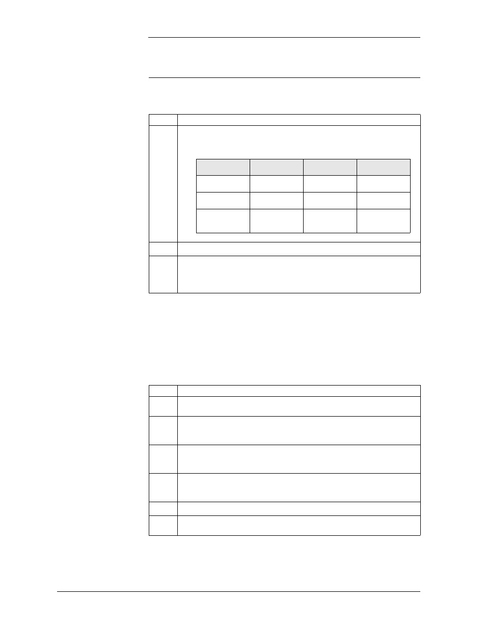
Is accessibility to the circuit throughout the network consistent with A2
requirements?
Voltage
Class
General Public
Employees
Craftspersons
A1
Restricted
Access
Exposed
Exposed
A2
Inaccessible
Restricted
Access
Exposed
A3
Inaccessible
Inaccessible
Restricted
Access
(Excsptions)
2
Is the 5-pin protector marked as a special circuit?
3
Does the 5-pin protector protect each pair to a level corresponding to a CommScope
3C*EW Gas tube primary protector? This protector has a voltage breakdown range
of 265-465 Volts and an impulse spark over range of <265-700 Volts. Protectors
with a lower voltage breakdown rating will be problematic.
To meet UL60950-21 specific procedural steps must be taken at the time of
installation. This section goes through those steps. These steps should be
performed before power is distributed in the network. Normally the final step
is performed by closing the circuit using a 5-pin protector after DC power is
applied to the system.
Step
Action
1
Recognize that the Remote Feed Telecommunication Voltage limited (RFT-V)
circuit is voltage limited to +190V and -190V from ground.
2
Is the total capacitance to ground on each line of the circuit less than 10 µF?
The QS882A introduces less than 1 µF. The sourcing electronics and line must
introduce less than 9 µF of capacitance.
3
Is the total capacitance line to line of the circuit less than 40 µF?
The QS882A introduces less than 1 µF. The sourcing electronics and line must
introduce less than 39 µF of capacitance from tip to ring.
4
Is the remote equipment also a RFT-V voltage limited circuit?
Both ends of the circuit must be designed to the same standard. This must be
verified before the equipment is connected together.
5
Is the voltage rating of the Network Wiring sufficient to support 190V to ground?
6
Is the chassis of the system bonded to ground?
Verify by both observation and measurement before powering the system.