Maximum output power, Installation category – GE Industrial Solutions CPS2500D +-190V User Manual
Page 17
CPS2500D +/-190V Downstream System
Issue 4 January 2008
Product Description 2 - 5
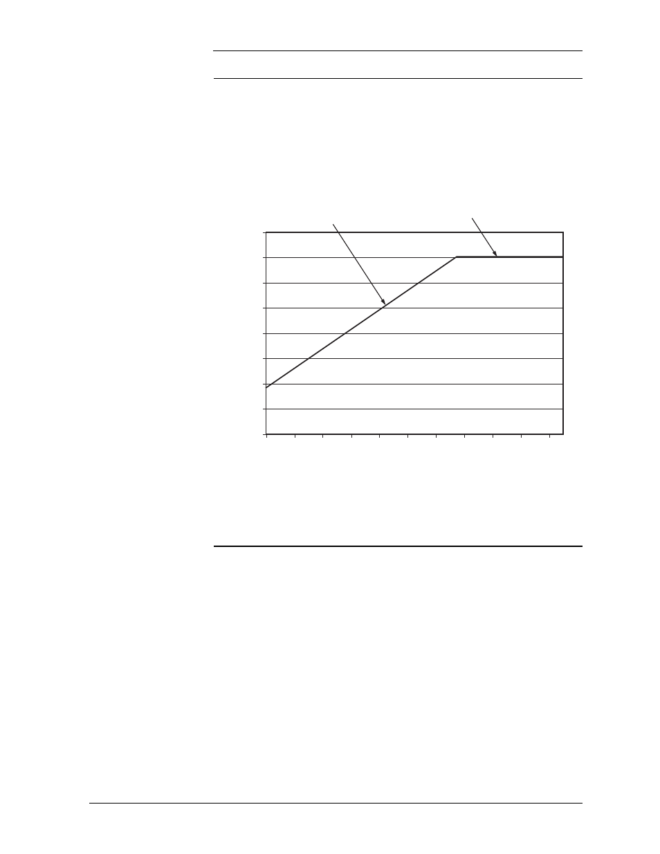
Maximum Output
Power
The following graph shows the low side tolerance output power from the pair
of dc/dc circuits on each unit, as input voltage delivered to the unit varies due
to losses in the copper feeder pairs. Efficiency is assumed to be linear with 84%
at Vin minimum of 190V (Pin =2 x (190 x 0.239) = 2 x 45.41W = 90.82W),
and 83% at Vin maximum of 380V; maximum input current is limited to 0.239
Amps at all input voltages.
Figure 2-2: Unit Maximum Output Power vs. Input Voltage
140.0
130.0
120.0
110.0
100.0
90.0
80.0
70.0
60.0
190
210
230
250
270
290
310
330
350
370
390
Output power limited by
maximum input current
Output power limited by
thermal dissipation
Unit Output Pow
er (per circuit p
air)
W
att
s
Input Voltage
Unit Maximum Output Power vs. Input Voltage when fed from +/-190V
upstream source.
Installation
category:
Input power shall be provided by up to 20 telephone wire pairs. The host
system must protect each pair to a level corresponding to a CommScope
3C*EW Gas tube primary protector. This protector has a voltage breakdown
range of 265-465 Volts and an impulse spark over range of <265-700 Volts.