Modbus gateway setup and connections, Connecting the power supply – B&B Electronics MESR424T_D-MT_D-SC - Manual User Manual
Page 15
3. Setup and Connections
15
3
3
.
.
M
M
o
o
d
d
b
b
u
u
s
s
G
G
a
a
t
t
e
e
w
w
a
a
y
y
S
S
e
e
t
t
u
u
p
p
a
a
n
n
d
d
C
C
o
o
n
n
n
n
e
e
c
c
t
t
i
i
o
o
n
n
s
s
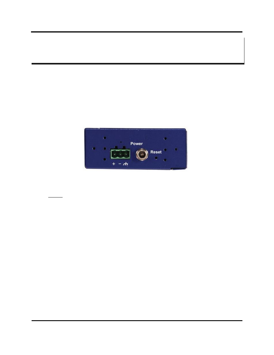
Connecting the Power Supply
Connect a DC power supply to the power terminals on the top of the MESR424 Modbus
Gateway. Polarity of the wires is indicated on the label on the side of the Modbus
gateway. Acceptable voltages are between 10 VDC and 48 VDC. The power supply must
be capable of supplying 6 W.
Figure 14. MESR Power Connection
NOTE: the terminal block must be used for Class 1 Division 2 applications; the barrel
jack cannot be used for these applications. See page 66 for further information.
Connecting MESR424 Modbus Gateways to Modbus networks
MESR424 Modbus Gateways can be configured to connect to Modbus networks using
RS-232, RS-422, RS-485 2-wire and RS-485 4-wire.
RS-232 connections support eight signal lines plus Signal Ground. Signals are single
ended and referenced to Ground. Default communications parameters are 9600, 8, N, 1
and no flow control implemented.
RS-422 connections support two signal pairs: RXA(-), RXB(+) and TXA(-), TXB(+),
plus GND. The data lines are differential pairs (A & B) in which the B line is positive
relative to the A line in the idle (mark) state. Ground provides a common mode reference.
RS-485 connections support 2-wire or 4-wire operation.
When configured for 4-wire operation the connection supports two signal pairs: RXA(-),
RXB(+) and TXA(-), TXB(+), plus GND. This makes full-duplex operation possible. The