Serial interface, Connecting the unit, Below – B&B Electronics 516TX-A - Manual User Manual
Page 14
(Revised 8/4/2009)
14
Connecting the Unit
For FX/FXE units, remove the dust cap from the fiber optic connectors and connect the fiber optic cables. The TX
port on the FX/FXE models should be connected to the RX port of the far end station. The RX port on the
FX/FXE versions should be connected to the TX port of the far end station.
For 10/100 Base-TX ports, plug a Category 5E twisted pair cable into the RJ45 connector. Connect the other end
to the far end station. Verify that the LNK LED’s are ON once the connection has been completed. To connect
any other port to another Switch or Repeater, use a standard Category 5 straight through or crossover cable.
Warning: Creating a port to port connection on the same switch (i.e. loop) is an illegal operation and will create a
broadcast storm which will crash the network!
Note: For units which have the N-View Option, you can validate that all ports are working correctly by installing
the N-View OPC Server software. The software is freely distributed on the ProductCD and our website
. Once the software is installed, you should view the Ports Counter page
to remotely monitor each connected port. You may find it helpful to copy [Alt]+[Print Screen] the Port Counter
information for each port and paste [Control]+[V] into a Windows document for further review. Please consult
your N-View OPC Server Manual for additional information.
Serial Interface
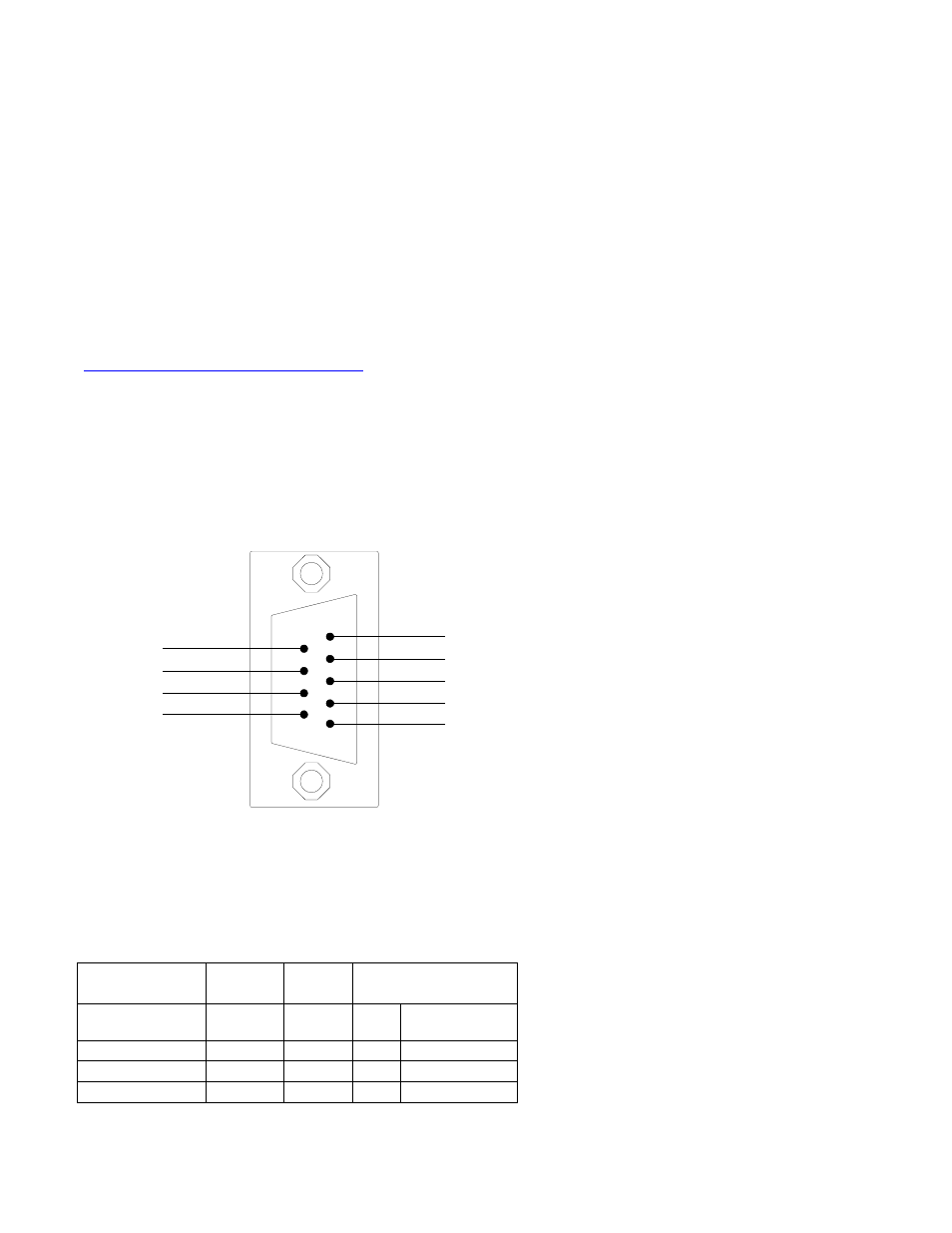
The 500 series switches provide an EIA-232 interface accessed via a 9 pin female connector (labeled ‘COM’ on
the unit). This is used to access the Command Line Interpreter (CLI). The pin-outs are shown
below:
Pin 6
Pin 7
Pin 8
Pin 9
Pin 1
TXD Pin 2
RXD Pin 3
Pin 4
GND Pin 5
Serial Cable
Connect the serial COM port of your PC and the 500 Series Switch using a standard straight through cable. You
will require a cable with a 9-pin or 25-pin sub-D female connector for the PC end, and a 9-pin male sub-D
connector for the series 500 end.
The following table shows the pin-out and the connections for both types of cable:
PC Port
25-Pin
9-Pin
500 series
Female
Female
9-Pin Male
Signal Name
Pin #
Pin #
Pin
#
Signal Name
TXD
2
3
3
RXD
RXD
3
2
2
TXD
GND
7
5
5
GND
Shielded cables and null modems are readily available from Radio Shack or a variety of computer shops.