B&B Electronics RT3G-300_310_320_330_340-W - User Manual User Manual
Page 32
B&B Electronics, Inc.
SPECTRE User Manual
32
SPECTRE_User_Manual_2912m
www.bb-elec.com
www.bb-europe.com
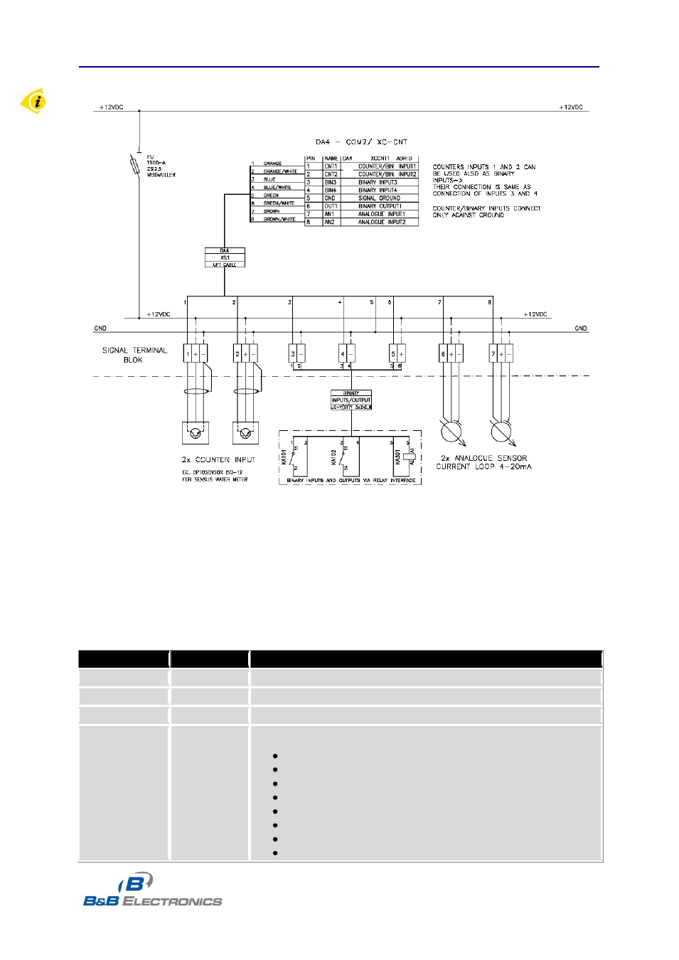
Typical connection of the I/O port circuits:
Fig. 29: Connection of the I/O Port circuitry
The I/O Port registers are read and written using MODBUS ASCII slave protocol over serial
port 1. Using this protocol, it is possible to configure the I/O board, read the input status, and control
the output. The I/O port communicates at 9600 baud, 8 bits, no parity, and 1 stop bit (8N1).
Address space
Address
Access
Description
0x0000
R/-
Firmware type
0x0001
R/-
Upper 16 bits of firmware version
0x0002
R/-
Lower 16 bits of firmware version
0x0003
R/-
Supports firmware characteristics
bit 0
– Analog input AN1
bit 1
– Analog input AN2
bit 2
– Counter input CNT1
bit 3
– Counter input CNT2
bit 4
– Binary input BIN1
bit 5
– Binary input BIN2
bit 6
– Binary input BIN3
bit 7
– Binary input BIN4
- USOPTL4DR-LS - Datasheet (2 pages)
- ZXT9-IOA-KIT - Manual (75 pages)
- ADAM-6066 - Manual (272 pages)
- 855-11619--57 - Datasheet (2 pages)
- 851-10904 - Datasheet (2 pages)
- SS-BLT-100PR - Quick Start Guide (1 page)
- ISOCON-6 - Datasheet (2 pages)
- I-7060 - Manual (64 pages)
- AMU864 - Datasheet (2 pages)
- 714FX6-SC_ST - Manual (154 pages)
- 422LP25R - Datasheet (2 pages)
- ZP9D-115RM-LR - Manual (54 pages)
- EKI-6311GN-EU - Manual (56 pages)
- ZZ24D-NA(NB,NC,ND)-SR - Quick Start Guide (4 pages)
- ESCLP-100 - Manual (23 pages)
- 806-39753 - Datasheet (1 page)
- 485SD9RJ - Datasheet (1 page)
- 712FX4-SC_ST - Manual (154 pages)
- 850-18610 - Manual (18 pages)
- ESW208 Series - Datasheet (2 pages)
- VESR321_ML_SL - Quick Start Guide (3 pages)
- OP10 - Datasheet (1 page)
- RT3G-300_310_320_330_340-W - Configuration Manual (79 pages)
- EIRHP305-T - Datasheet (2 pages)
- EIRSP1 - Datasheet (1 page)
- 422TTL33 - Datasheet (2 pages)
- 485DRCI - Quick Start Guide (2 pages)
- I-7021_P - Datasheet (2 pages)
- NTSA-CAT5E - Datasheet (2 pages)
- 485COSR - Datasheet (2 pages)
- 855-10619--57 - Datasheet (2 pages)
- UH401SL_2KV - Datasheet (2 pages)
- 105FXE-SC(ST)-15-POE - Manual (19 pages)
- 102MC-FL_SC_ST - Manual (23 pages)
- CBL00302 - Datasheet (1 page)
- 850-18100--27 - Datasheet (2 pages)
- 850-10953-DC - Datasheet (2 pages)
- ESR904 - Datasheet (2 pages)
- 308TX-N - Datasheet (3 pages)
- 422LP25N - Datasheet (2 pages)
- 708FX2-SC_ST - Datasheet (3 pages)
- MESR321_SL_ML - Datasheet (2 pages)
- SL2736-698 - Quick Start Guide (8 pages)
- I-7188E Series - Datasheet (1 page)
- ANT-PAD58-19 - Datasheet (1 page)