B&B Electronics RT3G-300_310_320_330_340-W - User Manual User Manual
Page 26
B&B Electronics, Inc.
SPECTRE User Manual
26
SPECTRE_User_Manual_2912m
www.bb-elec.com
www.bb-europe.com
Connector Pinout
Fig. 24: RS485/422 connector
RS-485 Mode
Pin
number
Signal mark
Description
Data flow direction
1
GND
Signal and supply ground
2
GND
Signal and supply ground
3
TxRx-
RS485 B (-)
Input/Output
4
TxRx+
RS485 A (+)
Input/Output
5
TxRx-
RS485 B (-)
Input/Output
6
TxRx+
RS485 A (+)
Input/Output
7
+12 V EXT External power supply
8
+12 V EXT External power supply
Table 12: Connector Pinout in RS-485 Mode
ATTENTION! The power supply is selected on the module board using
the jumpers.
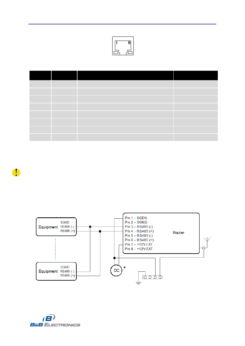
Note: In RS-485 mode, pins 3 and 5 and pins 4 and 6 are internally shorted together.
If galvanic separation is required, the converter must use an external power supply.
Fig. 25: Connection to the router with data cable length less than 10 m
- USOPTL4DR-LS - Datasheet (2 pages)
- ZXT9-IOA-KIT - Manual (75 pages)
- ADAM-6066 - Manual (272 pages)
- 855-11619--57 - Datasheet (2 pages)
- 851-10904 - Datasheet (2 pages)
- SS-BLT-100PR - Quick Start Guide (1 page)
- ISOCON-6 - Datasheet (2 pages)
- I-7060 - Manual (64 pages)
- AMU864 - Datasheet (2 pages)
- 714FX6-SC_ST - Manual (154 pages)
- 422LP25R - Datasheet (2 pages)
- ZP9D-115RM-LR - Manual (54 pages)
- EKI-6311GN-EU - Manual (56 pages)
- ZZ24D-NA(NB,NC,ND)-SR - Quick Start Guide (4 pages)
- ESCLP-100 - Manual (23 pages)
- 806-39753 - Datasheet (1 page)
- 485SD9RJ - Datasheet (1 page)
- 712FX4-SC_ST - Manual (154 pages)
- 850-18610 - Manual (18 pages)
- ESW208 Series - Datasheet (2 pages)
- VESR321_ML_SL - Quick Start Guide (3 pages)
- OP10 - Datasheet (1 page)
- RT3G-300_310_320_330_340-W - Configuration Manual (79 pages)
- EIRHP305-T - Datasheet (2 pages)
- EIRSP1 - Datasheet (1 page)
- 422TTL33 - Datasheet (2 pages)
- 485DRCI - Quick Start Guide (2 pages)
- I-7021_P - Datasheet (2 pages)
- NTSA-CAT5E - Datasheet (2 pages)
- 485COSR - Datasheet (2 pages)
- 855-10619--57 - Datasheet (2 pages)
- UH401SL_2KV - Datasheet (2 pages)
- 105FXE-SC(ST)-15-POE - Manual (19 pages)
- 102MC-FL_SC_ST - Manual (23 pages)
- CBL00302 - Datasheet (1 page)
- 850-18100--27 - Datasheet (2 pages)
- 850-10953-DC - Datasheet (2 pages)
- ESR904 - Datasheet (2 pages)
- 308TX-N - Datasheet (3 pages)
- 422LP25N - Datasheet (2 pages)
- 708FX2-SC_ST - Datasheet (3 pages)
- MESR321_SL_ML - Datasheet (2 pages)
- SL2736-698 - Quick Start Guide (8 pages)
- I-7188E Series - Datasheet (1 page)
- ANT-PAD58-19 - Datasheet (1 page)