Rs-485/422 ports – B&B Electronics RT3G-300_310_320_330_340-W - User Manual User Manual
Page 24
B&B Electronics, Inc.
SPECTRE User Manual
24
SPECTRE_User_Manual_2912m
www.bb-elec.com
www.bb-europe.com
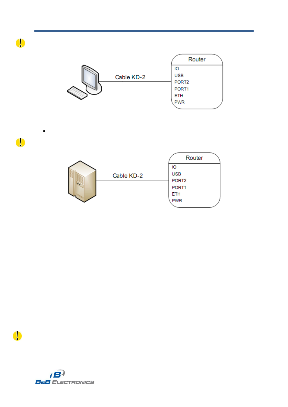
Example of a PC connection to the router:
Fig. 18: PC connection to router
Cable KD2 is connected to serial port PC (example COM1)
Example of the RS232 equipment connection to router (possibility to use all RS232 ports):
Fig. 19: RS-232 equipment connection to router
4.7.2 RS-485/422 Ports
The RS-485/422 ports can be powered using the internal 3.3V supply or by
connecting an external power supply to the port connector. External or internal power is
selected by jumpers J2 and J3 on the RS-485 module daughter board. To use internal
power, place jumpers J2 and J3 across pins 2 and 3. To select external power, jumpers J2
and J3 must be on pins 1 and 2.
Interface behavior of module Expansion port RS485/RS422 can be made by wiring
Jumpers J4, J5 and J6 on the RS-485 module select the mode of the port
– either RS-485 or
RS-422 mode. If RS485 is required, jumpers J4 and J5 must be connected and jumper J6
disconnected. If RS422 is required, jumpers J4 and J5 must be disconnected and jumper J6
connected.
Jumper placement can be seen in the picture below (RS-485 module is viewed from
the top).
Internal power supply should only be used in the event that it is not possible to
provide an external power supply.