Max3805, 7gbps adaptive receive equalizer, Functional diagram – Rainbow Electronics MAX3805 User Manual
Page 6
MAX3805
Input Stage with Equalization
The low-noise input stage of the MAX3805 includes two
amplifiers, one with flat frequency response and the
other with a highpass frequency response compensat-
ing for the loss characteristic of 6-mil FR-4 PC board
transmission line. A current-steering network, imple-
mented with a pair of variable attenuators feeding into a
common summing node, provides the means to contin-
uously vary the amount of equalization. The amount of
equalization is controlled by feedback from two power-
detector blocks that set the variable attenuators to
match the loss of a particular transmission path.
Dual Power-Detector Feedback Loop
The MAX3805 adapts the equalizer to a specific path
loss by sampling the output of the summing node with a
pair of frequency-dependent power detectors. The first
power detector has a lowpass bandwidth of 500MHz; the
second power detector has full bandwidth.
NRZ PRBS data has a sin
2
(f)/f
2
spectral characteristic.
When this data is passed through a lossy FR-4 path,
high-frequency components are attenuated, while low-
10.7Gbps Adaptive Receive Equalizer
6
_______________________________________________________________________________________
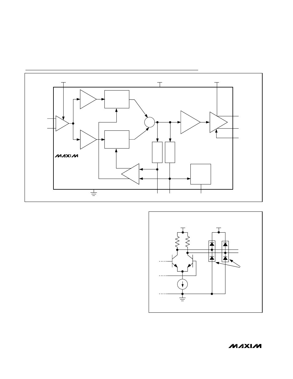
∑
MAX3805
CML IN
FLAT
AMP
BOOST
AMP
VARIABLE
ATTENUATOR
VARIABLE
ATTENUATOR
LIMITING
AMP
CML OUT
LF POWER
DETECTOR
POWER
DETECTOR
LOOP
FILTER
SIGNAL
DETECT
LFPD
HFPD
SD
EN
SDO-
SDO+
SDI+
SDI-
V
CC1
V
CC
V
CC2
Functional Diagram
50
Ω
50
Ω
ESD
STRUCTURES
V
CC
V
CC2
OUT+
OUT-
Figure 1. CML Output Structure