Table 22. dop module registers – Rainbow Electronics MAX1464 User Manual
Page 36
MAX1464
Low-Power, Low-Noise Multichannel
Sensor Signal Processor
36
______________________________________________________________________________________
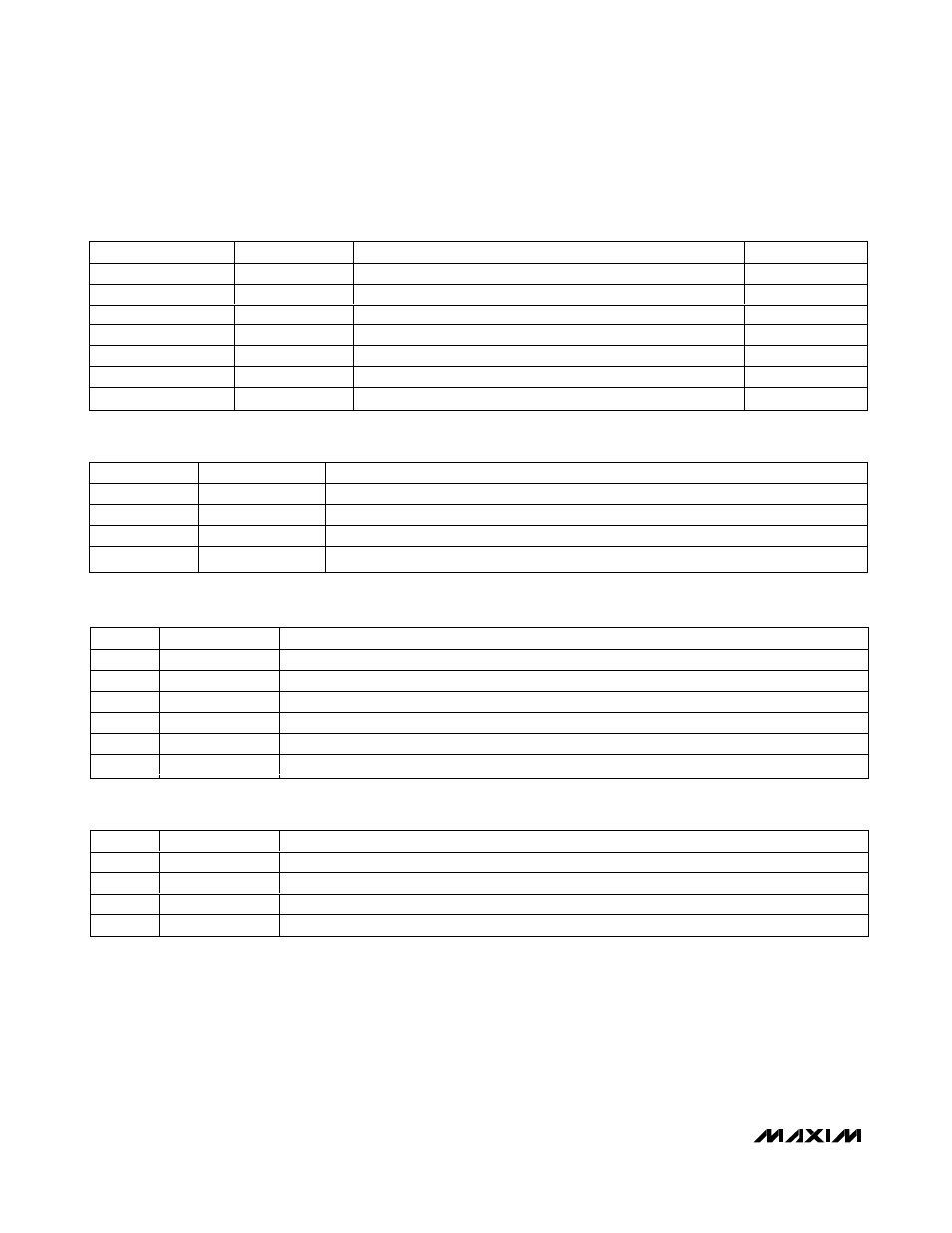
BIT
NAME
DESCRIPTION
15–9
—
Unused.
8
SELPWM1
Select PWM1 output: 1 = OUT1LG, 0 = OUT1SM.
7–5
—
Unused.
4
SELDAC1
Select DAC1 output: 1 = OUT1LG (large op-amp buffer), 0 = OUT1SM (small op-amp buffer).
3–1
—
Unused.
0
SELREF1
Select voltage reference for DAC1: 0 = V
DD
, 1 = 2 x V
REF
.
Table 24. DOP1_Config (Address = 12h)
BIT
NAME
DESCRIPTION
15–5
—
Unused.
4
ENPWM2
Enable pulse-width modulator 2: 1 = PWM2 active, 0 = PWM2 inactive.
3–1
—
Unused.
0
ENDAC2
Enable digital-to-analog converter 2: 1 = DAC2 active, 0 = DAC2 inactive.
Table 25. DOP2_Control (Address = 14h)
NAME
ADDRESS
DESCRIPTION
POR VALUE
DOP1_Data
10h
DAC1/PWM1 input data.
0000
DOP1_Control
11h
Initiate DAC1 and/or PWM1 conversions.
0000
DOP1_Config
12h
DAC1/PWM1 output and DAC 1 reference selection.
0000
DOP2_Data
13h
DAC2/PWM2 input data.
0000
DOP2_Control
14h
Initiate DAC2 and/or PWM2 conversions.
0000
DOP2_Config
15h
DAC2/PWM2 output and DAC 2 reference selection.
0000
OpAmp_Config
30h
Settings for op amps in DOPn modules.
0000
Table 22. DOP Module Registers
BIT
NAME
DESCRIPTION
15–5
—
Unused.
4
ENPWM1
Enable pulse-width modulator 1: 1 = PWM1 active, 0 = PWM1 inactive.
3–1
—
Unused.
0
ENDAC1
Enable digital-to-analog converter 1: 1 = DAC1 active, 0 = DAC1 inactive.
Table 23. DOP1_Control (Address = 11h)