Table 12. adc_config_ta (address = 08h), Table 13. adc_config_tb (address = 09h), 4mhz) – Rainbow Electronics MAX1464 User Manual
Page 32
MAX1464
Low-Power, Low-Noise Multichannel
Sensor Signal Processor
32
______________________________________________________________________________________
BIT
NAME
DESCRIPTION
15–7
—
Unused.
6–4
BIAS2[2:0]
ADC bias setting to use during conversion of channel 2. BIAS2[2] = MSB.
3–2
—
Unused.
1–0
REF2[1:0]
Reference select for conversion on channel 2. REF2[2] = MSB.
Table 11. ADC_Config_2B (Address = 06h)
BITS
NAME
DESCRIPTION
15–11
PGAT[4:0]
Programmable gain to use during conversion of temperature sensor. PGAT[4] = MSB.
10–8
CLKT[2:0]
ADC clock setting to use during conversion of the temperature sensor. CLKT[2] = MSB.
7
—
Unused.
6–4
REST[2:0]
ADC resolution setting to use during conversion of the temperature sensor. REST[2] = MSB.
3
COT[3]
Coarse-offset DAC sign bit.
2–0
COT[2:0]
Coarse-offset DAC setting to use during conversion of the temperature sensor. COT[2] = MSB.
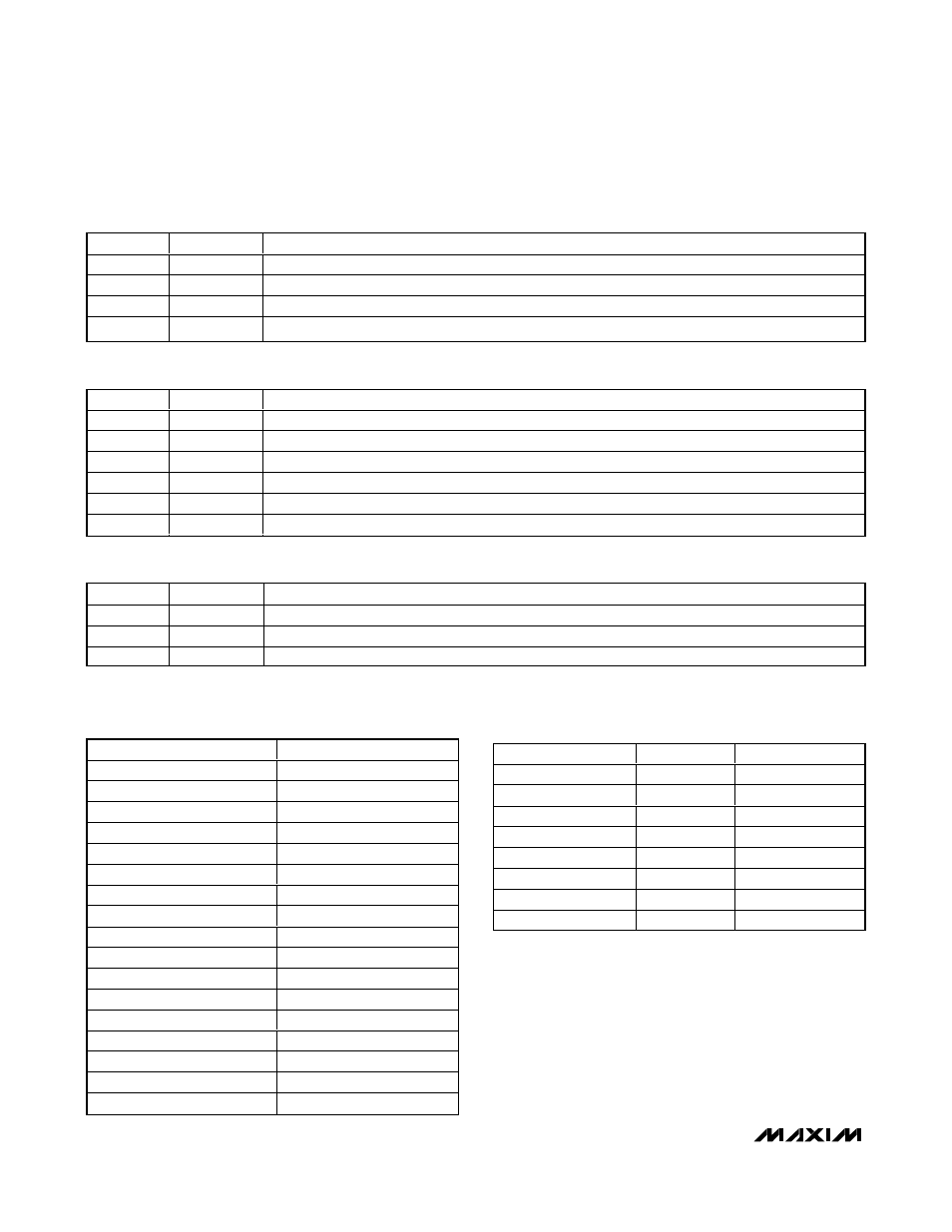
Table 12. ADC_Config_TA (Address = 08h)
BITS
NAME
DESCRIPTION
15–7
—
Unused.
6–4
BIAST[2:0]
ADC bias setting to use during conversion of the temperature sensor. BIAST[2] = MSB.
3–0
—
Unused.
Table 13. ADC_Config_TB (Address = 09h)
PGAn[4:0]
GAIN (V/V)
00000
0.99
00001
7.7
00010
15.5
00011
23
00100
31
00101
39
00110
46
00111
54
01000
62
01010
77
01100
92
01110
107
10000
123
10100
153
11000
183
11100
214
11110
244
Table 14. Programmable-Gain Amplifier
(PGAn[4:0], Where n = 1, 2, or T)
CLKn[2:0]
DIVISOR n
f
ADC
(Hz)
000
4
1M
001
8
500k
010
16
250k
011
32
125k
100
64
62.5 k
101
128
31.25k
110
256
15.625k
111
512
7.8125k
Table 15. ADC Clock (CLKn[2:0],
Where n = 1, 2, or T; f
CLK
= 4MHz)