Pin description – Rainbow Electronics MAX1464 User Manual
Page 11
MAX1464
Low-Power, Low-Noise Multichannel
Sensor Signal Processor
______________________________________________________________________________________
11
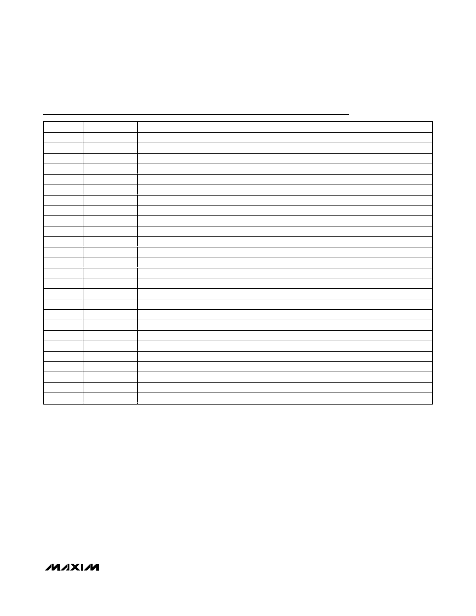
Pin Description
PIN
NAME
FUNCTION
1
OUT1SM
Small Op Amp 1 Output
2
AMP1M
Op Amp 1 Negative Input
3
AMP1P
Op Amp 1 Positive Input
4
OUT1LG
Large Op Amp 1 Output
5, 7
N.C.
No Connection
6
V
DD
Positive Supply Voltage Input. Bypass V
DD
to V
SS
with a 0.1µF ceramic capacitor.
8
CKSEL
Clock-Select Digital Input
9
CKIO
Clock Digital Input/Output
10
CS
SPI Chip-Select Digital Input. Active low.
11
DO
SPI Data Output
12
DI
SPI Data Input
13
SCLK
SPI Interface Clock
14, 19
V
SS
Negative Power-Supply Input
15
V
DDF
Positive Supply Voltage for FLASH Memory. Bypass V
DDF
to V
SS
with a 0.1µF ceramic capacitor.
16
GPIO1
General-Purpose Digital Input/Output 1
17
GPIO2
General-Purpose Digital Input/Output 2
18
V
SSF
Negative Power-Supply Input for FLASH Memory
20
INM2
Negative Input for ADC Channel 2
21
INP2
Positive Input for ADC Channel 2
22
INM1
Negative Input for ADC Channel 1
23
INP1
Positive Input for ADC Channel 1
24
V
REF
External Reference Voltage Input for ADC and DACs
25
OUT2LG
Large Op Amp 2 Output
26
AMP2P
Op Amp 2 Positive Input
27
AMP2M
Op Amp 2 Negative Input
28
OUT2SM
Small Op Amp 2 Output