Table 3. module registers, Table 4. adc module registers – Rainbow Electronics MAX1464 User Manual
Page 29
MAX1464
Low-Power, Low-Noise Multichannel
Sensor Signal Processor
______________________________________________________________________________________
29
MODULE
NAME
REGISTER
NAME
ADDRESS
DESCRIPTION
R/W
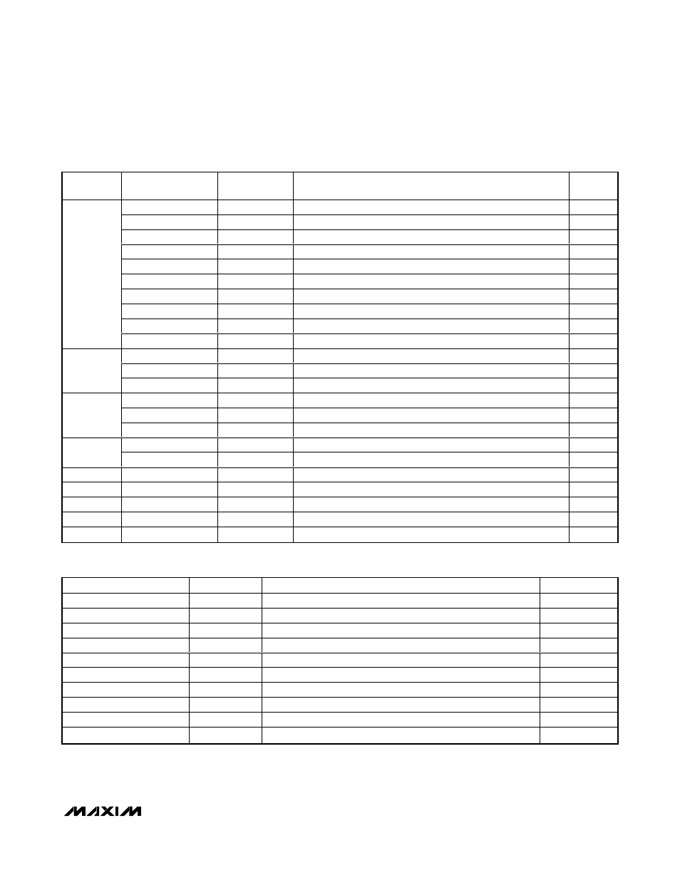
ADC_Control
00h
Initiate conversions and select ADC input.
R/
W
ADC_Data_1
01h
Result of ADC conversion on channel 1 input.
R
ADC_Config_1A
02h
Settings for channel 1 input and conversion.
R/
W
ADC_Config_1B
03h
Settings for channel 1 input and conversion.
R/
W
ADC_Data_2
04h
Result of ADC conversion on channel 2 input.
R
ADC_Config_2A
05h
Settings for channel 2 input and conversion.
R/
W
ADC_Config_2B
06h
Settings for channel 2 input and conversion.
R/
W
ADC_Data_T
07h
Result of ADC conversion on temperature input.
R
ADC_Config_TA
08h
Settings for temperature input and conversion.
R/
W
ADC
ADC_Config_TB
09h
Settings for temperature input and conversion.
R/
W
DOP1_Data
10h
Input setting for the analog DAC and digital PWM outputs.
R/
W
DOP1_Control
11h
Enable and reference selection.
R/
W
DOP1
DOP1_Config
12h
Select DAC or PWM output.
R/
W
DOP2_Data
13h
Input setting for the analog DAC and digital PWM outputs.
R/
W
DOP2_Control
14h
Enable and reference selection.
R/
W
DOP2
DOP2_Config
15h
Select DAC or PWM output.
R/
W
TMR_Control
20h
Initiate timer.
R/
W
Timer
TMR_Config
21h
Set prescaler value and timeout value.
R/
W
Op Amp
Opamp_Config
30h
Set op amps as unity-gain buffers.
R/
W
Power
PO_Control
31h
Turn on power to modules with power-control function.
R/
W
Oscillator
OSC_Control
32h
Trim oscillator frequency, enable clock input/output.
R/
W
GPIO1
GPIO1_Control
40h
Enable I/O, set output value, read input value.
R/
W
GPIO2
GPIO2_Control
41h
Enable I/O, set output value, read input value.
R/
W
Table 3. Module Registers
NAME
ADDRESS
DESCRIPTION
POR VALUE
ADC_Control
00h
Initiate conversions and set signal source.
0000h
ADC_Data_1
01h
Result of ADC conversion on channel 1 input.
0000h
ADC_Config_1A
02h
Settings for channel 1 input and conversion.
0000h
ADC_Config_1B
03h
Settings for channel 1 input and conversion.
0070h
ADC_Data_2
04h
Result of ADC conversion on channel 2 input.
0000h
ADC_Config_2A
05h
Settings for channel 2 input and conversion.
0000h
ADC_Config_2B
06h
Settings for channel 2 input and conversion.
0070h
ADC_Data_T
07h
Result of ADC conversion on temperature input.
0000h
ADC_Config_TA
08h
Settings for temperature input and conversion.
0000h
ADC_Config_TB
09h
Settings for temperature input and conversion.
0070h
Table 4. ADC Module Registers