3 read sector lockdown registers, Sck cs si so – Rainbow Electronics AT25DF081A User Manual
Page 27
27
8715C–SFLSH–11/2012
AT25DF081A
10.3
Read Sector Lockdown Registers
The Sector Lockdown Registers can be read to determine the current lockdown status of each physical 64-Kbyte
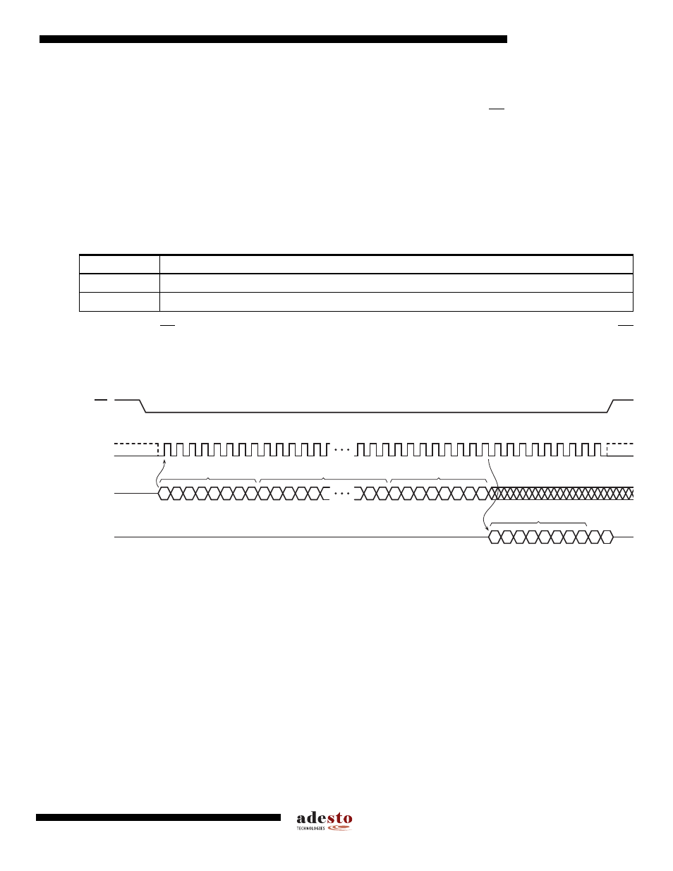
sector. To read the Sector Lockdown Register for a particular 64-Kbyte sector, the CS pin must first be asserted
and the opcode of 35h must be clocked in. Once the opcode has been clocked in, three address bytes designating
any address within the 64-Kbyte sector must be clocked in. After the address bytes have been clocked in, data will
be output on the SO pin during every subsequent clock cycle. The data being output will be a repeating byte of
either FFh or 00h to denote the value of the appropriate Sector Lockdown Register.
At clock frequencies above f
CLK
, the first byte of data output will not be valid. Therefore, if operating at clock fre-
quencies above f
CLK
, at least two bytes of data must be clocked out from the device in order to determine the
correct status of the appropriate Sector Lockdown Register.
Deasserting the CS pin will terminate the read operation and put the SO pin into a high-impedance state. The CS
pin can be deasserted at any time and does not require that a full byte of data be read.
Figure 10-3. Read Sector Lockdown Register
Table 10-2.
Read Sector Lockdown Register – Output Data
Output Data
Sector Lockdown Register Value
00h
Sector Lockdown Register value is 0 (sector is not locked down)
FFh
Sector Lockdown Register value is 1 (sector is permanently locked down)
SCK
CS
SI
SO
MSB
MSB
2
3
1
0
0
0
1
1
0
1
0
1
6
7
5
4
10 11
9
8
12
39
42 43
41
40
37 38
33
36
35
34
31 32
29 30
44
47 48
46
45
OPCODE
A
A
A
A
A
A
A
A
A
MSB
X
X
X
X
X
X
X
X
MSB
MSB
D
D
D
D
D
D
D
D
D
D
ADDRESS BITS A23-A0
DON'T CARE
DATA BYTE
HIGH-IMPEDANCE