2 freeze sector lockdown state, Figure 10-1. sector lockdown, Sck cs si so – Rainbow Electronics AT25DF081A User Manual
Page 26
26
8715C–SFLSH–11/2012
AT25DF081A
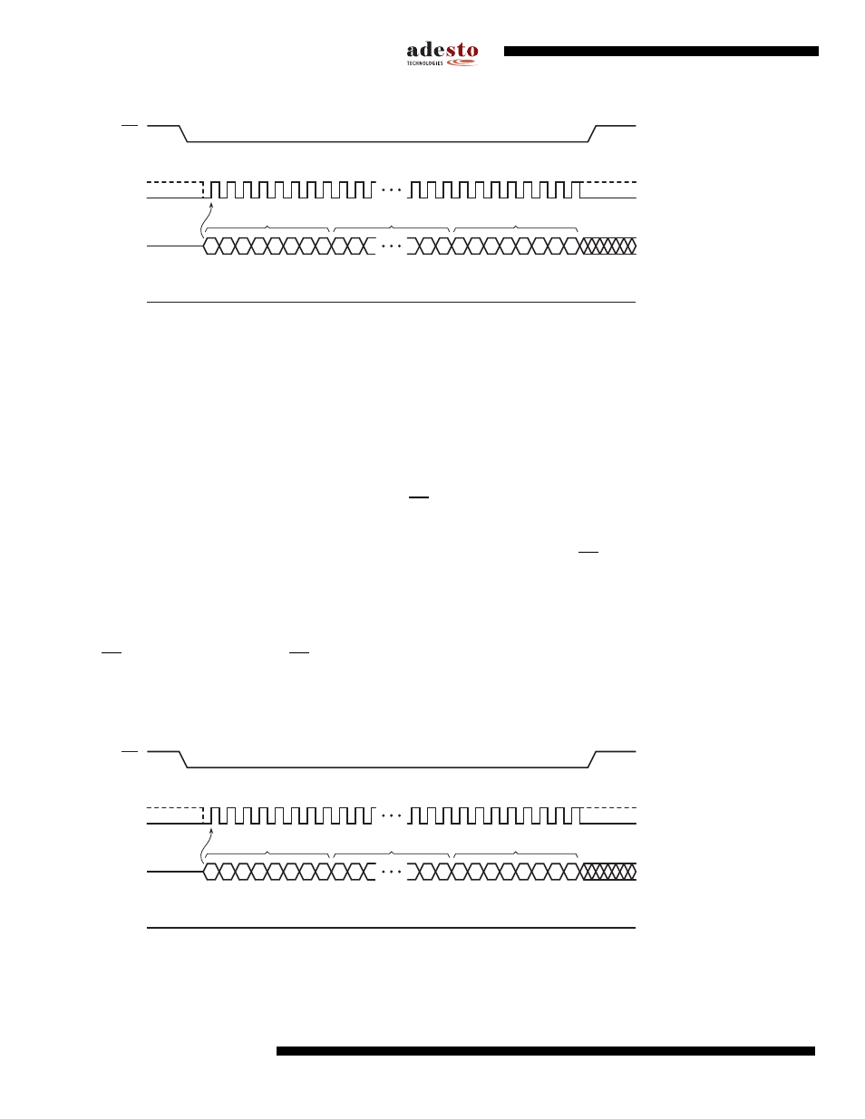
Figure 10-1. Sector Lockdown
10.2
Freeze Sector Lockdown State
The current sector lockdown state can be permanently frozen so that no further modifications to the Sector Lock-
down Registers can be made; therefore, the Sector Lockdown command will be permanently disabled, and no
additional sectors can be locked down aside from those already locked down. Any attempts to issue the Sector
Lockdown command after the sector lockdown state has been frozen will be ignored.
Before the Freeze Sector Lockdown State command can be issued, the Write Enable command must have been
previously issued to set the WEL bit in the Status Register to a logical “1”. In addition, the Sector Lockdown
Enabled (SLE) bit in the Status Register must have also been previously set to the logical “1” state. To issue the
Freeze Sector Lockdown State command, the CS pin must first be asserted and the opcode of 34h must be
clocked into the device followed by three command specific address bytes of 55AA40h. After the three address
bytes have been clocked in, a confirmation byte of D0h must be clocked in immediately following the three address
bytes. Any additional data clocked into the device will be ignored. When the CS pin is deasserted, the current sec-
tor lockdown state will be permanently frozen within a time of t
LOCK
. In addition, the WEL bit in the Status Register
will be reset back to the logical “0” state, and the SLE bit will be permanently reset to a logical “0” to indicate that
the Sector Lockdown command is permanently disabled.
The complete and correct three address bytes and the confirmation byte must be clocked into the device before the
CS pin is deasserted, and the CS pin must be deasserted on an even byte boundary (multiples of eight bits); other-
wise, the device will abort the operation. When the device aborts the Freeze Sector Lockdown State operation, the
WEL bit in the Status Register will be reset to a logical “0”; however, the state of the SLE bit will be unchanged.
Figure 10-2. Freeze Sector Lockdown State
SCK
CS
SI
SO
MSB
MSB
2
3
1
0
0
0
1
1
0
0
1
1
6
7
5
4
9
8
39
37 38
33
36
35
34
31 32
29 30
OPCODE
HIGH-IMPEDANCE
A
A
A
A
A
A
MSB
1
1
0
1
0
0
0
0
ADDRESS BITS A23-A0
CONFIRMATION BYTE IN
SCK
CS
SI
SO
MSB
MSB
2
3
1
0
0
0
1
1
0
1
0
0
6
7
5
4
9
8
39
37 38
33
36
35
34
31 32
29 30
OPCODE
HIGH-IMPEDANCE
0
1
0
0
0
0
MSB
1
1
0
1
0
0
0
0
ADDRESS BITS A23-A0
CONFIRMATION BYTE IN