7 protected states and the write protect (wp) pin – Rainbow Electronics AT25DF081A User Manual
Page 24
24
8715C–SFLSH–11/2012
AT25DF081A
9.7
Protected States and the Write Protect (WP) Pin
The WP pin is not linked to the memory array itself and has no direct effect on the protection status or lockdown
status of the memory array. Instead, the WP pin, in conjunction with the SPRL (Sector Protection Registers
Locked) bit in the Status Register, is used to control the hardware locking mechanism of the device. For hardware
locking to be active, two conditions must be met-the WP pin must be asserted and the SPRL bit must be in the log-
ical “1” state.
When hardware locking is active, the Sector Protection Registers are locked and the SPRL bit itself is also locked.
Therefore, sectors that are protected will be locked in the protected state, and sectors that are unprotected will be
locked in the unprotected state. These states cannot be changed as long as hardware locking is active, so the Pro-
tect Sector, Unprotect Sector, and Write Status Register commands will be ignored. In order to modify the
protection status of a sector, the WP pin must first be deasserted, and the SPRL bit in the Status Register must be
reset back to the logical “0” state using the Write Status Register command. When resetting the SPRL bit back to a
logical “0”, it is not possible to perform a Global Protect or Global Unprotect at the same time since the Sector Pro-
tection Registers remain soft-locked until after the Write Status Register command has been executed.
If the WP pin is permanently connected to GND, then once the SPRL bit is set to a logical “1”, the only way to reset
the bit back to the logical “0” state is to power-cycle the device. This allows a system to power-up with all sectors
software protected but not hardware locked. Therefore, sectors can be unprotected and protected as needed and
then hardware locked at a later time by simply setting the SPRL bit in the Status Register.
When the WP pin is deasserted, or if the WP pin is permanently connected to V
CC
, the SPRL bit in the Status Reg-
ister can still be set to a logical “1” to lock the Sector Protection Registers. This provides a software locking ability
to prevent erroneous Protect Sector or Unprotect Sector commands from being processed. When changing the
SPRL bit to a logical “1” from a logical “0”, it is also possible to perform a Global Protect or Global Unprotect at the
same time by writing the appropriate values into bits five, four, three, and two of the first byte of the Status
Register.
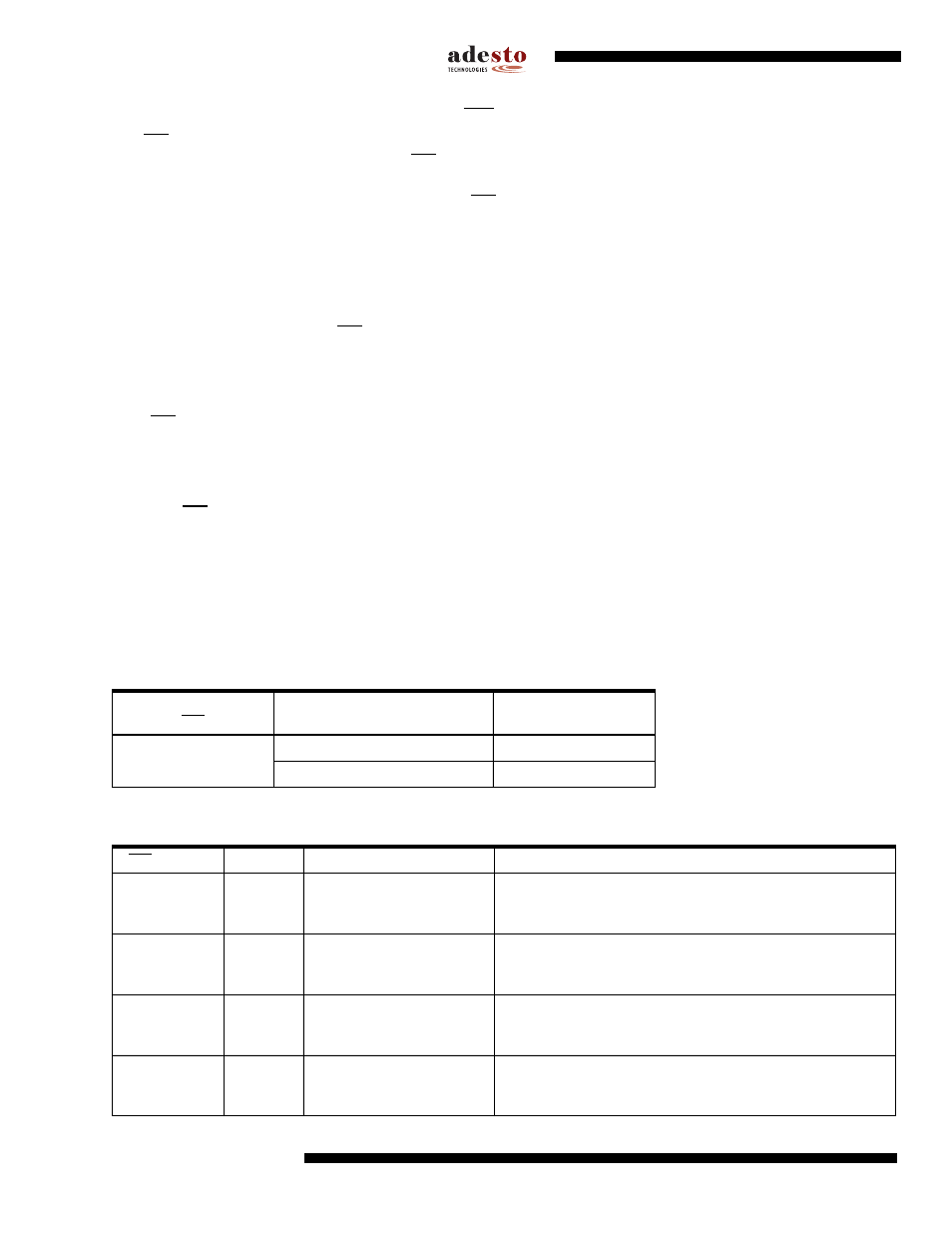
Tables
and
detail the various protection and locking states of the device.
Note:
1. “n” represents a sector number
Table 9-4.
Sector Protection Register States
WP
Sector Protection Register
Sector
n
X
(Don't Care)
0
Unprotected
1
Protected
Table 9-5.
Hardware and Software Locking
WP
SPRL
Locking
SPRL Change Allowed
Sector Protection Registers
0
0
Can be modified from 0 to 1
Unlocked and modifiable using the Protect and Unprotect
Sector commands. Global Protect and Unprotect can also be
performed.
0
1
Hardware
Locked
Locked
Locked in current state. Protect and Unprotect Sector
commands will be ignored. Global Protect and Unprotect
cannot be performed.
1
0
Can be modified from 0 to 1
Unlocked and modifiable using the Protect and Unprotect
Sector commands. Global Protect and Unprotect can also be
performed.
1
1
Software
Locked
Can be modified from 1 to 0
Locked in current state. Protect and Unprotect Sector
commands will be ignored. Global Protect and Unprotect
cannot be performed.