2 input matching at lna_in – Rainbow Electronics ATA5746 User Manual
Page 6
6
4596A–RKE–05/06
ATA5745/ATA5746 [Preliminary]
2.2
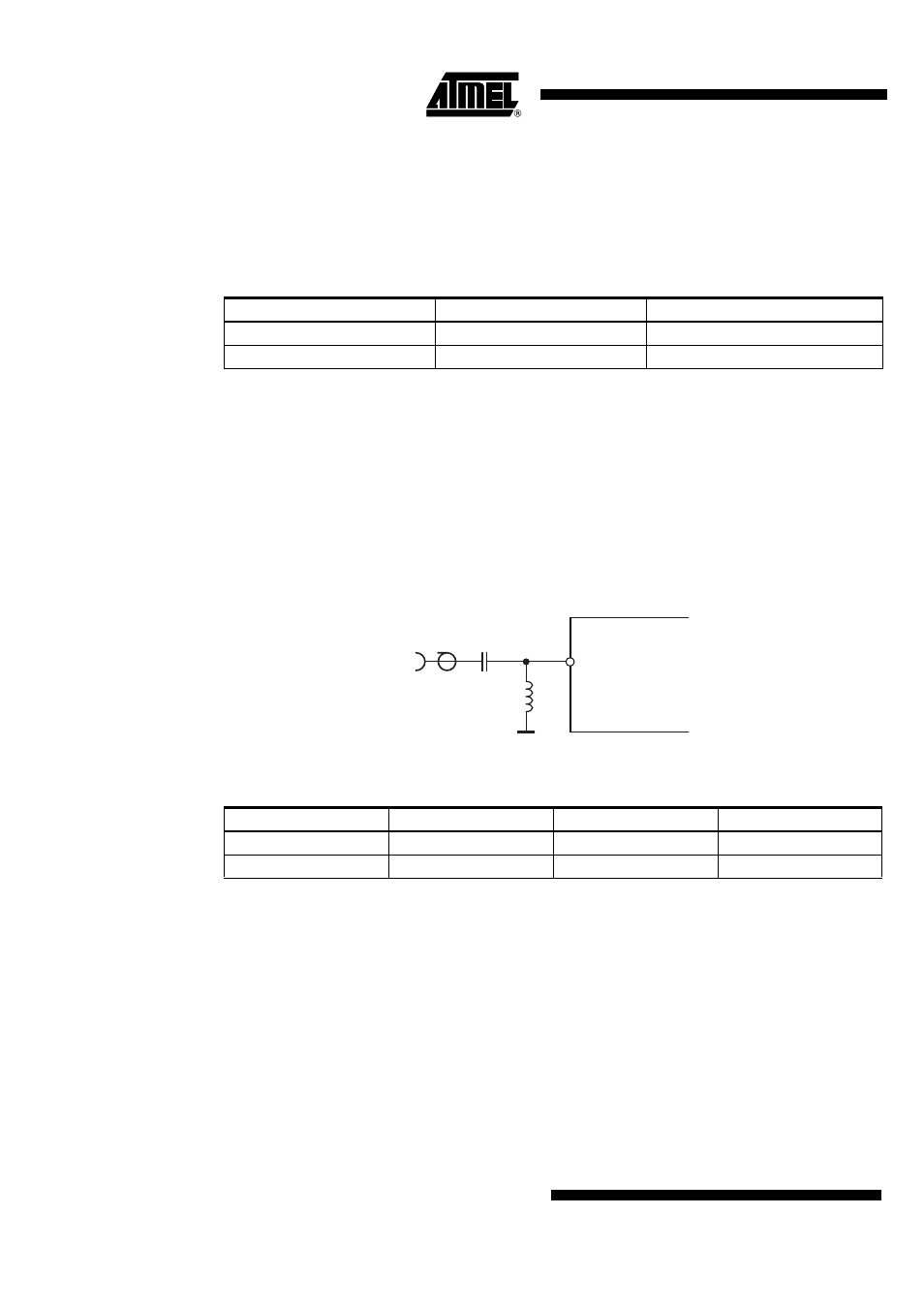
Input Matching at LNA_IN
The measured input impedances as well as the values of a parallel equivalent circuit of these
impedances can be seen in
. The highest sensitivity is achieved with power matching
of these impedances to the source impedance.
The matching of the LNA input to 50
Ω is done using the circuit shown in
ues of the matching elements given in
. The reflection coefficients were always
≤ –10 dB. Note that value changes of C1 and L1 may be necessary to compensate individual
board layout parasitics. The measured typical FSK and ASK Manchester-code sensitivities with
a bit error rate (BER) of 10
–3
are shown in
and
. These measure-
ments were done with wire-wound inductors having quality factors reported in
,
resulting in estimated matching losses of 0.8 dB at 315 MHz and 433.92 MHz. These losses can
be estimated when calculating the parallel equivalent resistance of the inductor with
R
loss
= 2
× π × f × L × Q
L
and the matching loss with 10 log(1+R
In_p
/ R
loss
).
Figure 2-1.
Input Matching to 50
Ω
Table 2-1.
Measured Input Impedances of the LNA_IN Pin
f
RF
[MHz]
Z
In
(RF_IN) [
Ω]
R
In_p
//C
In_p
[pF]
315
(72.4 – j298)
1300
Ω//1.60
433.92
(55 – j216)
900
Ω//1.60
Table 2-2.
Input Matching to 50
Ω
f
RF
[MHz]
C
1
[pF]
L
1
[nH]
Q
L1
315
2.2
68
20
433.92
2.2
36
15
RF
IN
14
C1
L1
LNA_IN
ATA5745/ATA5746