Electrical characteristics: general (continued) – Rainbow Electronics ATA5746 User Manual
Page 35
35
4596A–RKE–05/06
ATA5745/ATA5746 [Preliminary]
f
RF
= 433.92 MHz
CLK_OUT division ratio
= 3
= 6
= 12
CLK_OUT has nominal
50% duty cycle
3
f
CLK_OUT
4.52458
2.26229
1.13114
MHz
D
f
RF
= 315 MHz
CLK_OUT division ratio
= 3
= 6
= 12
CLK_OUT has nominal
50% duty cycle
3
f
CLK_OUT
4.3811
2.190
1.0952
MHz
D
4.10 DC voltage after startup
V
DC
(XTAL1, XTAL2)
XTO running (Standby
mode, Active mode)
7,8
V
DCXTO
–250
–45
mV
C
5
Synthesizer
5.1
Spurs in Active mode
At ±f
CLK_OUT
,
CLK_OUT enabled
(division ratio = 3)
f
RF
= 315 MHz
f
RF
= 433.92 MHz
SP
RX
–75
–70
dBC
C
at ±f
XTO
f
RF
= 315 MHz
f
RF
= 433.92 MHz
SP
RX
–75
–70
dBC
A
5.2
Phase noise at 3 MHz
Active mode
f
RF
= 315 MHz
f
RF
= 433.92 MHz
L
RX3M
–130
–127
dBC/Hz
A
5.3
Phase noise at 20 MHz
Active mode
Noise floor
L
RX20M
–135
–132
dBC/Hz
B
6
Microcontroller Interface
6.1
CLK_OUT output rise and
fall time
f
CLK_OUT
< 4.5 MHz
C
L
= 10 pF
C
L
= Load capacitance on
pin CLK_OUT
2.7V
≤ V
VS5V
≤ 3.3V or
4.5V
≤ V
VS5V
≤ 5.5V
20% to 80% V
VS5V
3
t
rise
t
fall
20
20
30
30
ns
ns
B
6.2
Internal equivalent
capacitance
Used for current
calculation
3
C
CLK_OUT
8
pF
B
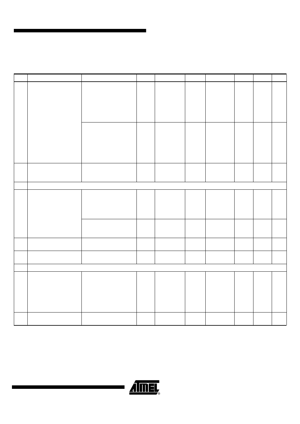
13. Electrical Characteristics: General (Continued)
All parameters refer to GND and are valid for T
amb
= –40°C to +105°C, V
VS3V_AVCC
= V
VS5V
= 2.7V to 3.3V, and V
VS5V
= 4.5V to 5.5V.
Typical values are given at V
VS3V_AVCC
= V
VS5V
= 3V, T
amb
= 25°C, and f
RF
= 315 MHz unless otherwise specified. Details about current
consumption, timing, and digital pin properties can be found in the specific sections of the “Electrical Characteristics”.
No. Parameters
Test Conditions
Pin
(1)
Symbol
Min.
Typ.
Max.
Unit
Type*
*) Type means: A = 100% tested, B = 100% correlation tested, C = Characterized on samples, D = Design parameter
Note:
1. Pin numbers in parenthesis were measured with RF_IN matched to 50
Ω according to
Figure 2-1 on page 6
with component
values as in
Table 2-2 on page 6
(RF
IN
).