Polling current calculation – Rainbow Electronics ATA5746 User Manual
Page 26
26
4596A–RKE–05/06
ATA5745/ATA5746 [Preliminary]
8.
Polling Current Calculation
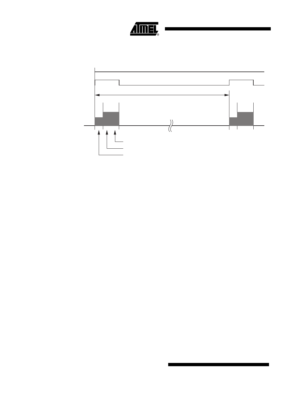
Figure 8-1.
Polling Cycle
In an RKE and TPM system, the average chip current in Polling mode, I
Polling
, is an important
parameter. The polling period must be controlled by the connected microcontroller via the pins
ENABLE and RX. The polling current can be calculated as follows:
I
Polling
= (T
Startup_PLL
/ T
Polling_Period
)
× I
Startup_PLL
+ (T
Startup_Sig_Proc
/ T
Polling_Period
)
× I
Active
+
(T
Bitcheck
/ T
Polling_Period
)
× I
Active
+ (T
Polling_Period
– T
Startup_PLL
– T
Startup_Sig_Proc
– T
Bitcheck
) /
T
Polling_Period
× I
Standby
T
Startup_PLL
:
depends on 315 MHz/433.92 MHz application.
T
Startup_Sig_Proc
:
depends on 315 MHz/433.92 MHz application and the selected bit
rate range.
T
Bitcheck
:
depends on the signal bit rate (1 / Signal_Bit_Rate).
T
Polling_Period
:
depends on the transmitter telegram (preburst).
I
Startup_PLL
:
depends on 3V or 5V application and the setting of pin CLK_OUT.
I
Active
:
depends on 3V or 5V application, ASK or FSK mode and the setting of
pin CLK_OUT.
I
Standby
:
depends on 3V or 5V application and the setting of pin CLK_OUT.
Example:-
315-MHz application (ATA5746), bit rate: 9.6 Kbits/s, T
Polling_Period
= 8 ms
--> T
Startup_PLL
=
269 µs
--> T
Startup_Sig_Proc
=
324 µs
(Bit Rate Range 3)
--> T
Bitcheck
=
104 µs
3V application; ASK mode, CLK_OUT disabled
--> I
Startup_PLL
=
4.5 mA
--> I
Active
=
6.5 mA
--> I
Standby
=
0.05 mA
--> I
Polling
= 0.545 mA
I
Standby
I
Standby
I
Active
I
Star
tup_PLL
I
Active
I
Star
tup_PLL
RX
I
Supply
ENABLE
T
Bitcheck
(= 1 / Signal_Bitrate (average)
T
Startup_PLL
(Startup RF-PLL)
T
Startup_Sig_Proc
(Startup Signal Processing)