Electrical characteristics: general (continued) – Rainbow Electronics ATA5746 User Manual
Page 30
30
4596A–RKE–05/06
ATA5745/ATA5746 [Preliminary]
2.4
Active mode start-up time
From Standby mode to
Active mode
BR_Range_3
ATA5745
ATA5746
T
Startup_PLL
+
T
Startup_Sig_Proc
565
593
µs
µs
A
3
Active Mode
3.1
Supply current Active
mode
V
VS3V_AVCC
= V
VS5V
= 3V
ASK mode
CLK_OUT disabled
SENSE_CTRL = 0
10,11
I
Active
6.5
mA
A
V
VS3V_AVCC
= V
VS5V
= 3V
FSK mode
CLK_OUT disabled
SENSE_CTRL = 0
10,11
I
Active
6.7
mA
A
V
VS5V
= 5V
ASK mode
CLK_OUT disabled
SENSE_CTRL = 0
10
I
Active
6.7
mA
A
V
VS5V
= 5V
FSK mode
CLK_OUT disabled
SENSE_CTRL = 0
10
I
Active
6.9
mA
A
3.2
Supply current Polling
mode
V
VS3V_AVCC
= V
VS5V
= 3V
T
Polling_Period
= 8 ms
BR_Range_3, ASK mode,
CLK_OUT disabled
Data rate = 9.6 Kbits/s
10,11
I
Polling
545
µA
C
3.3
Input sensitivity FSK
f
RF
= 315 MHz
FSK deviation
f
DEV
= ±38 kHz
BER = 10
–
3
T
amb
= 25°C
Bit rate 9.6 Kbits/s BR2
(14)
P
REF_FSK
–103
–105
–106.5
dBm
B
Bit rate 2.4 Kbits/s BR0
(14)
P
REF_FSK
–106
–108
–109.5
dBm
B
FSK deviation ±18 kHz to
±50 kHz
Bit rate 9.6 Kbits/s BR2
(14)
P
REF_FSK
–101
dBm
B
Bit rate 2.4 Kbits/s BR0
(14)
P
REF_FSK
–104
dBm
B
3.4
Input sensitivity ASK
f
RF
= 315 MHz
ASK 100% level of carrier,
BER = 10
–
3
T
amb
= 25°C
Bit rate 9.6 Kbits/s BR2
(14)
P
REF_ASK
–109
–111
–112.5
dBm
B
Bit rate 2.4 Kbits/s BR0
(14)
P
REF_ASK
–112
–114
–115.5
dBm
B
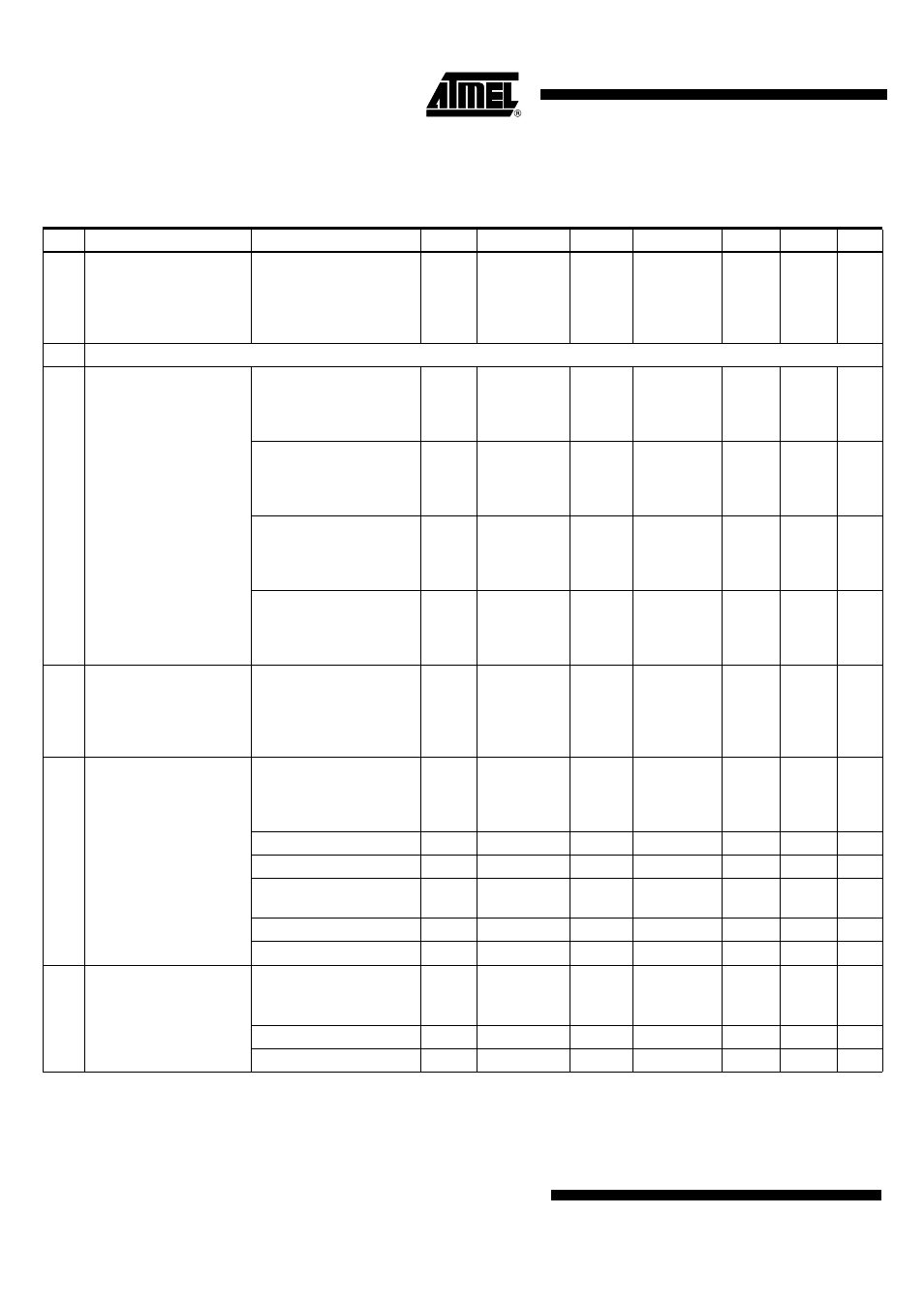
13. Electrical Characteristics: General (Continued)
All parameters refer to GND and are valid for T
amb
= –40°C to +105°C, V
VS3V_AVCC
= V
VS5V
= 2.7V to 3.3V, and V
VS5V
= 4.5V to 5.5V.
Typical values are given at V
VS3V_AVCC
= V
VS5V
= 3V, T
amb
= 25°C, and f
RF
= 315 MHz unless otherwise specified. Details about current
consumption, timing, and digital pin properties can be found in the specific sections of the “Electrical Characteristics”.
No. Parameters
Test Conditions
Pin
(1)
Symbol
Min.
Typ.
Max.
Unit
Type*
*) Type means: A = 100% tested, B = 100% correlation tested, C = Characterized on samples, D = Design parameter
Note:
1. Pin numbers in parenthesis were measured with RF_IN matched to 50
Ω according to
Figure 2-1 on page 6
with component
values as in
Table 2-2 on page 6
(RF
IN
).