Rainbow Electronics AT90S8515 User Manual
Page 82
82
AT90S8515
0841G–09/01
1.
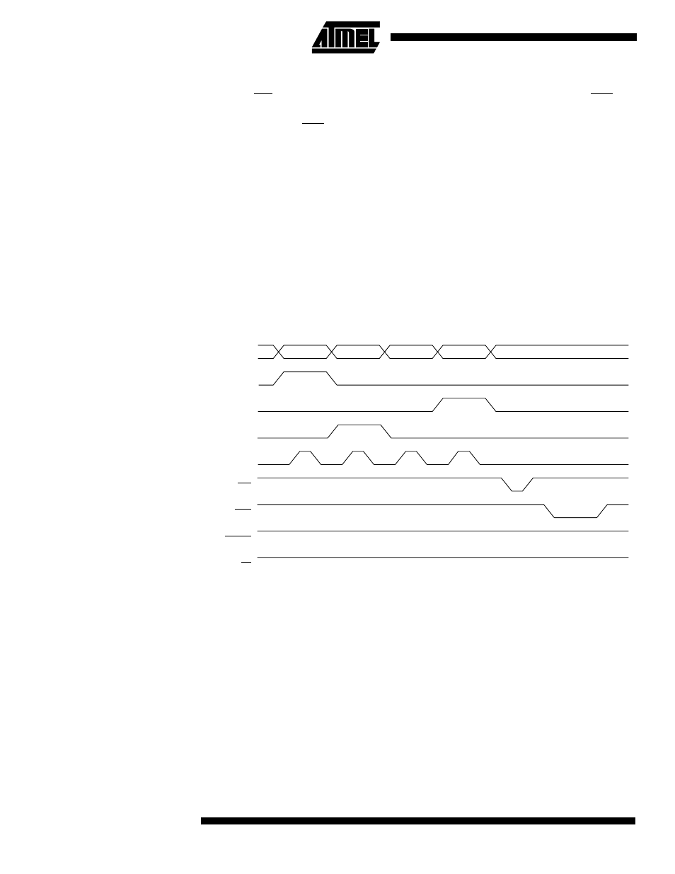
Set BS to “1”. This selects high data.
2.
Give WR a negative pulse. This starts programming of the data byte. RDY/BSY
goes low.
3.
Wait until RDY/BSY goes high to program the next byte.
(See Figure 62 for signal waveforms.)
The loaded command and address are retained in the device during programming. For
efficient programming, the following should be considered:
•
The command needs only be loaded once when writing or reading multiple memory
locations.
•
Address high byte needs only be loaded before programming a new 256-word page
in the Flash.
•
Skip writing the data value $FF, that is, the contents of the entire Flash and
EEPROM after a Chip Erase.
These considerations also apply to EEPROM programming and Flash, EEPROM and
signature byte reading.
Figure 61. Programming the Flash Waveforms
$10
ADDR. HIGH
ADDR. LOW
DATA LOW
DATA
XA1
XA0
BS
XTAL1
WR
RDY/BSY
RESET
OE
12V
- MAX5151 (16 pages)
- MAXQ3108 (64 pages)
- MAX5661 (39 pages)
- MAX6691 (7 pages)
- MAX5362 (12 pages)
- ADC10158 (26 pages)
- MAX8922L (14 pages)
- MAX8596Z (8 pages)
- MAX7491 (18 pages)
- MAX15040 (15 pages)
- MAX5177 (16 pages)
- ADC08138 (22 pages)
- MAX5961 (42 pages)
- T89C51RD2 (86 pages)
- MAX16055 (9 pages)
- MAX6659 (17 pages)
- ADC0820 (20 pages)
- MAX6678 (19 pages)
- MAX8884Z (15 pages)
- MAX16915 (9 pages)
- MAX8620 (18 pages)
- MAX5144 (12 pages)
- MAX6670 (8 pages)
- MAX8760 (39 pages)
- W78C32C (14 pages)
- MX7533 (8 pages)
- MAX8727 (13 pages)
- MAX9053 (15 pages)
- W78C54 (16 pages)
- MAX8614B (15 pages)
- W90N740 (219 pages)
- MAX6626 (13 pages)
- ADC10738 (30 pages)
- MAX17000 (31 pages)
- MAX5051 (21 pages)
- MAXQ1004 (18 pages)
- MAX6871 (51 pages)
- MX7847 (12 pages)
- MAX6608 (6 pages)
- MAX17083 (15 pages)
- MAX6641 (17 pages)
- MAX5251 (16 pages)
- MAX6338 (8 pages)
- MAX6690 (16 pages)
- MAX8668 (18 pages)