Interface to external sram – Rainbow Electronics AT90S8515 User Manual
Page 60
60
AT90S8515
0841G–09/01
using the SBI or CBI instruction, ACI will be cleared if it has become set before the
operation.
• Bit 3 – ACIE: Analog Comparator Interrupt Enable
When the ACIE bit is set (one) and the I-bit in the Status Register is set (one), the Ana-
log Comparator interrupt is activated. When cleared (zero), the interrupt is disabled.
• Bit 2 – ACIC: Analog Comparator Input Capture Enable
When set (one), this bit enables the Input Capture function in Timer/Counter1 to be trig-
gered by the Analog Comparator. The comparator output is, in this case, directly
connected to the Input Capture front-end logic, making the comparator utilize the noise
canceler and edge select features of the Timer/Counter1 Input Capture interrupt. When
cleared (zero), no connection between the Analog Comparator and the Input Capture
function is given. To make the comparator trigger the Timer/Counter1 Input Capture
interrupt, the TICIE1 bit in the Timer Interrupt Mask Register (TIMSK) must be set (one).
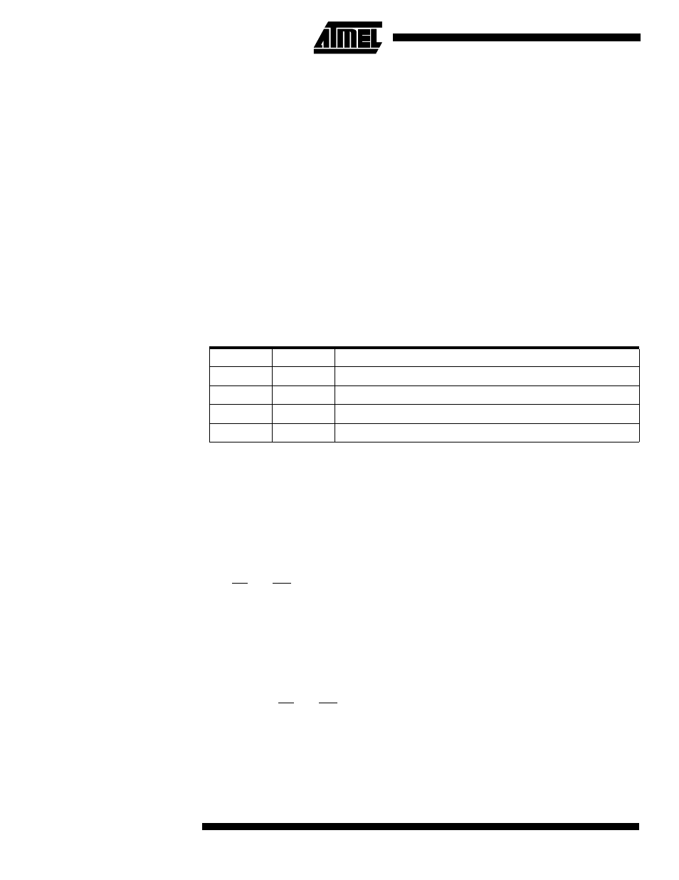
• Bits 1, 0 – ACIS1, ACIS0: Analog Comparator Interrupt Mode Select
These bits determine which comparator events trigger the Analog Comparator interrupt.
The different settings are shown in Table 18.
Note:
When changing the ACIS1/ACIS0 bits, the Analog Comparator interrupt must be dis-
abled by clearing its interrupt enable bit in the ACSR register. Otherwise an interrupt can
occur when the bits are changed.
Interface to External
SRAM
The interface to the SRAM consists of:
Port A: Multiplexed low-order address bus and data bus
Port C: High-order address bus
The ALE pin: Address latch enable
The RD and WR pins: Read and write strobes
The external data SRAM is enabled by setting the SRE (external SRAM enable) bit of
the MCUCR (MCU Control Register) and will override the setting of the Data Direction
Register (DDRA). When the SRE bit is cleared (zero), the external data SRAM is dis-
abled and the normal pin and data direction settings are used. When SRE is cleared
(zero), the address space above the internal SRAM boundary is not mapped into the
internal SRAM, as AVR parts do not have an interface to the external SRAM.
When ALE goes from high to low, there is a valid address on Port A. ALE is low during a
data transfer. RD and WR are active when accessing the external SRAM only.
When the external SRAM is enabled, the ALE signal may have short pulses when
accessing the internal RAM, but the ALE signal is stable when accessing the external
SRAM.
Figure 42 sketches how to connect an external SRAM to the AVR using eight latches
that are transparent when G is high.
Table 18. ACIS1/ACIS0 Settings
ACIS1
ACIS0
Interrupt Mode
0
0
Comparator Interrupt on Output Toggle
0
1
Reserved
1
0
Comparator Interrupt on Falling Output Edge
1
1
Comparator Interrupt on Rising Output Edge