Rainbow Electronics AT90S8515 User Manual
Page 41
41
AT90S8515
0841G–09/01
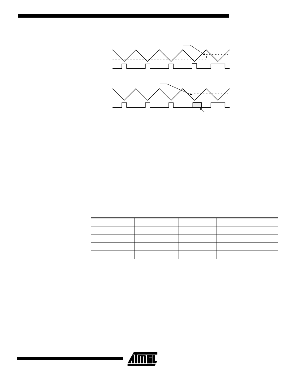
Figure 32. Effects on Unsynchronized OCR1 Latching
During the time between the write and the latch operation, a read from OCR1A or
OCR1B will read the contents of the temporary location. This means that the most
recently written value always will read out of OCR1A/B.
When the OCR1 contains $0000 or TOP, the output OC1A/OC1B is updated to low or
high on the next compare match according to the settings of COM1A1/COM1A0 or
COM1B1/COM1B0. This is shown in Table 13.
Note:
If the compare register contains TOP value and the prescaler is not in use (CS12..CS10
= 001), the PWM output will not produce any pulse at all, because up-counting and
down-counting values are reached simultaneously. When the prescaler is in use
(CS12..CS10
≠ 001 or 000), the PWM output goes active when the counter reaches the
TOP value; but the down-counting compare match is not interpreted to be reached
before the next time the counter reaches the TOP value, making a one-period PWM
pulse.
Note:
X = A or B
In PWM mode, the Timer Overflow Flag1 (TOV1) is set when the counter advances from
$0000. Timer Overflow Interrupt1 operates exactly as in normal Timer/Counter mode,
i.e., it is executed when TOV1 is set, provided that Timer Overflow Interrupt1 and global
interrupts are enabled. This also applies to the Timer Output Compare1 flags and
interrupts.
Table 13. PWM Outputs OCR1X = $0000 or TOP
COM1X1
COM1X0
OCR1X
Output OC1X
1
0
$0000
L
1
0
TOP
H
1
1
$0000
H
1
1
TOP
L
Counter Value
Compare Value
PWM Output OC1X
Synchronized
OCR1X Latch
Counter Value
Compare Value
PWM Output OC1X
Unsynchronized
OCR1X Latch
Glitch
Compare Value changes
Note: X = A or B
Compare Value changes