Program and data addressing modes, Register direct, single register rd – Rainbow Electronics AT90S8515 User Manual
Page 13
13
AT90S8515
0841G–09/01
two additional clock cycles is used per byte. This has the following effect: Data transfer
instructions take two extra clock cycles, whereas interrupt, subroutine calls and returns
will need four clock cycles more than specified in the instruction set manual.
The five different addressing modes for the data memory cover: Direct, Indirect with Dis-
placement, Indirect, Indirect with Pre-decrement and Indirect with Post-increment. In the
register file, registers R26 to R31 feature the indirect addressing pointer registers.
The direct addressing reaches the entire data space.
The Indirect with Displacement mode features 63 address locations reached from the
base address given by the Y- or Z-register.
When using register indirect addressing modes with automatic pre-decrement and post-
increment, the address registers X, Y and Z are decremented and incremented.
The 32 general-purpose working registers, 64 I/O registers, the 512 bytes of internal
data SRAM, and the 64K bytes of optional external data SRAM in the AT90S8515 are all
accessible through all these addressing modes.
See the next section for a detailed description of the different addressing modes.
Program and Data
Addressing Modes
The AT90S8515 AVR RISC microcontroller supports powerful and efficient addressing
modes for access to the program memory (Flash) and data memory (SRAM, Register
file and I/O memory). This section describes the different addressing modes supported
by the AVR architecture. In the figures, OP means the operation code part of the instruc-
tion word. To simplify, not all figures show the exact location of the addressing bits.
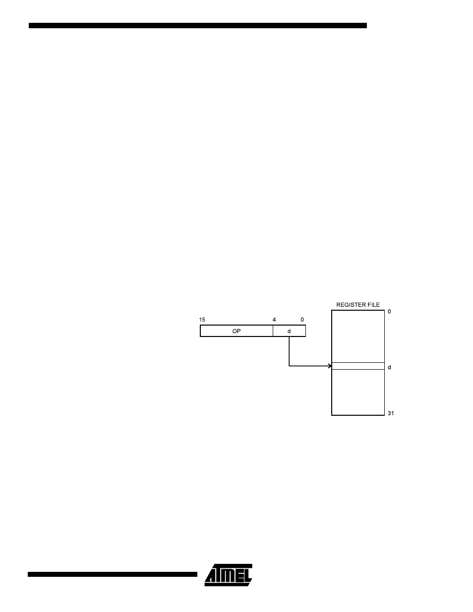
Register Direct, Single
Register RD
Figure 9. Direct Single Register Addressing
The operand is contained in register d (Rd).