Reset sources – Rainbow Electronics AT90S8515 User Manual
Page 23
23
AT90S8515
0841G–09/01
$00f
ldi r16,low(RAMEND)
$010
out SPL,r16
$011
xxx
…
…
…
…
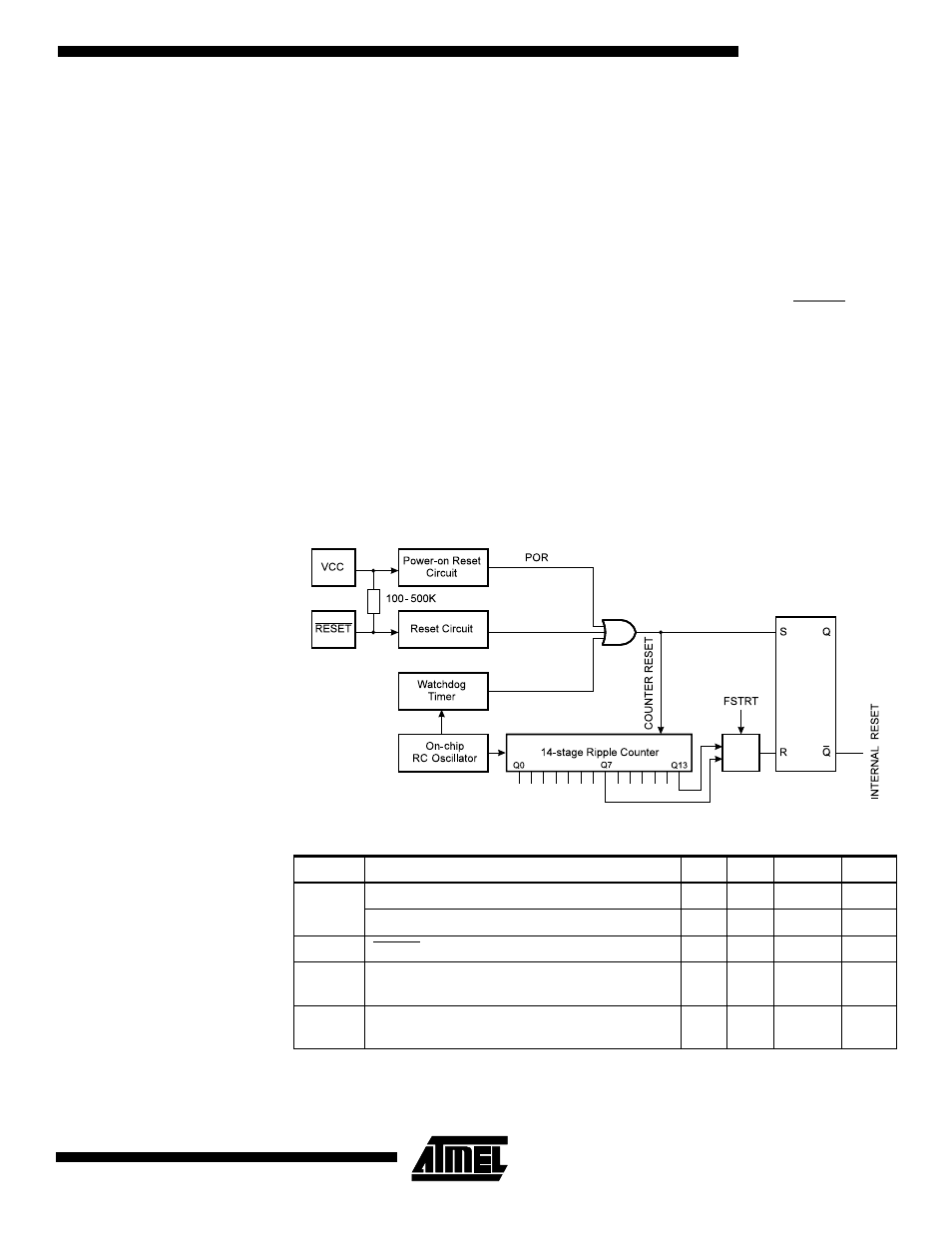
Reset Sources
The AT90S8515 has three sources of reset:
•
Power-on Reset. The MCU is reset when the supply voltage is below the Power-on
Reset threshold (V
POT
).
•
External Reset. The MCU is reset when a low level is present on the RESET pin for
more than 50 ns.
•
Watchdog Reset. The MCU is reset when the Watchdog timer period expires and
the Watchdog is enabled.
During reset, all I/O registers are set to their initial values and the program starts execu-
tion from address $000. The instruction placed in address $000 must be an RJMP
(relative jump) instruction to the reset handling routine. If the program never enables an
interrupt source, the interrupt vectors are not used and regular program code can be
placed at these locations. The circuit diagram in Figure 23 shows the reset logic. Table 3
defines the timing and electrical parameters of the reset circuitry.
Figure 23. Reset Logic
Note:
The Power-on Reset will not work unless the supply voltage has been below V
POT
(falling).
Table 3. Reset Characteristics
Symbol
Parameter
Min
Typ
Max
Units
V
POT
Power-on Reset Threshold Voltage (rising)
0.8
1.2
1.6
V
Power-on Reset Threshold Voltage (falling)
0.2
0.4
0.6
V
V
RST
RESET Pin Threshold Voltage
–
–
0.9 V
CC
V
t
TOUT
Reset Delay Time-out Period FSTRT
Unprogrammed
11.0
16.0
21.0
ms
t
TOUT
Reset Delay Time-out Period FSTRT
Programmed
0.25
0.28
0.31
ms