Max6948b, Pin description pin configuration – Rainbow Electronics MAX6948B User Manual
Page 8
High-Efficiency PWM LED Driver with Boost
Converter and Five Constant-Current GPIO Ports
8
MAX6948B
Pin Description
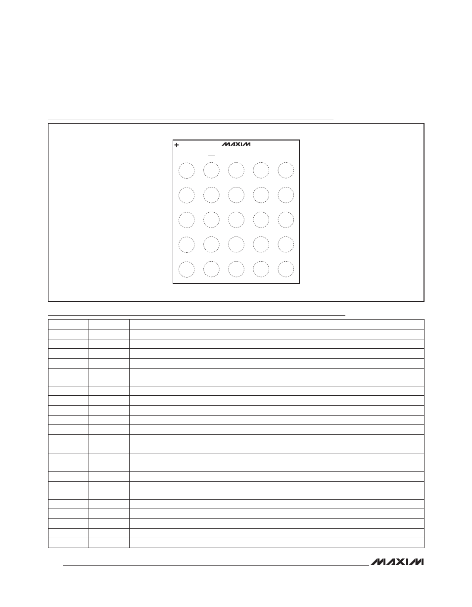
Pin Configuration
MAX6948B
TOP VIEW
(BUMP IN BOTTOM)
WLP
(2.31mm x 2.31mm)
A1
P0
P1
A2
A3
A4
A5
B1
B2
B3
B4
B5
SCL
SDA
V+
VDD
AD0
V+
V+
P2
GND
N.C.
I.C.
COMP
P3
GND
FB
PGND
PGND
P4
OUT
LEDSW
LX
LX
RST
C1
C2
C3
C4
C5
D1
D2
D3
D4
D5
E1
E2
E3
E4
E5
PIN
NAME
FUNCTION
A1
P0
GPIO Port. Open-drain I/O. P0 can be configured as a 30mA (max) constant sink current output.
A2
RST
Active-Low Reset Input
A3
SCL
I
2
C-Compatible, Serial-Clock Input
A4
SDA
I
2
C-Compatible, Serial-Data I/O
A5, B4, B5
V+
Boost-Converter Supply Voltage and Positive Supply Voltage. Bypass V+ to GND with a 2.2FF or
higher value ceramic capacitor.
B1
P1
GPIO Port. Open-drain I/O. P1 can be configured as a 30mA (max) constant sink current output.
B2
V
DD
I
2
C Logic Supply Voltage. Bypass V
DD
to GND with a 0.1FF or higher value ceramic capacitor.
B3
AD0
Address Input. AD0 selects up to four device slave addresses (Table 13).
C1
P2
GPIO Port. Open-drain I/O. P2 can be configured as a 10mA (max) constant sink current output.
C2, D2
GND
Ground. Connect to PGND.
C3
N.C.
No Connection. Internally not connected.
C4
I.C.
Internally Connected. Connect I.C. to GND for normal operation.
C5
COMP
Compensation Terminal for the Boost Converter. A capacitor from COMP to PGND determines the
boost-converter stability.
D1
P3
GPIO Port. Open-drain I/O. P3 can be configured as a 10mA maximum constant sink current output.
D3
FB
Load Current-Sense Voltage Feedback for the Boost Converter. A resistor between FB and PGND
sets the maximum load current.
D4, D5
PGND
Power Ground. Connect PGND to GND.
E1
P4
GPIO Port. Open-drain I/O. P4 can be configured as a 10mA (max) constant sink current output.
E2
OUT
Output Voltage Sense Input for Boost Converter
E3
LEDSW
High-Voltage, Constant-Current Input. Connect LEDSW to the cathode-end of the WLED string.
E4, E5
LX
Inductor Switch Node