Max6948b, Electrical characteristics (continued) – Rainbow Electronics MAX6948B User Manual
Page 3
High-Efficiency PWM LED Driver with Boost
Converter and Five Constant-Current GPIO Ports
3
MAX6948B
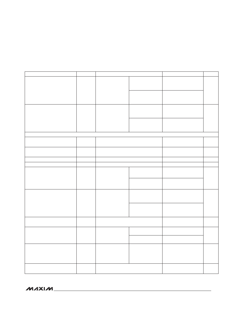
ELECTRICAL CHARACTERISTICS (continued)
(Typical Application Circuit, V+ = 2.7V to 5.0V, V
DD
= 1.7V to V+, T
A
= T
MIN
to T
MAX
, unless otherwise noted. Typical values are at
V+ = 3.3V, V
DD
= 2.5V, T
A
= +25NC.) (Note 4)
PARAMETER
SYMBOL
CONDITIONS
MIN
TYP
MAX
UNITS
Change in Supply Current per
30mA Port
D
I
DD30
One port set to
30mA constant cur-
rent; all other ports
are digital inputs at
V
DD
or GND
T
A
= +25NC
3
6.2
mA
T
A
= T
MIN
to T
MAX
7
Change in Supply Current per
10mA Port
D
I
DD10
One port set to 5mA
constant current
half-current setting;
all other ports are
digital inputs at V
DD
or GND
T
A
= +25NC
1.3
1.7
mA
T
A
= T
MIN
to T
MAX
2
GPIO PORTS (P0–P4)
Input High Voltage
V
IH1
Port I/O register value set to 0x01
(0.7 x
V
DD
)
V
Input Low Voltage
V
IL1
Port I/O register value set to 0x01
(0.3 x
V
DD
)
V
Input Leakage Current
I
IN
±0.03
Q
1
F
A
Input Capacitance
10
pF
30mA Port Sink Constant Current
(P0, P1)
I
PORT30
Port I/O register
value set to 0x02,
V+ = 3.3V, V
EXT
-
V
LED
= 0.5V to 1.5V
(Note 5)
T
A
= +25NC
27
30
34
mA
T
A
= T
MIN
to T
MAX
25
35
10mA Port Sink Constant Current
(P2, P3, P4)
I
PORT10
5mA half-current
setting, port I/O
register value set
to 0x02, V+ = 3.3V,
V
EXT
- V
LED
= 0.5V
to 1.5V (Note 5)
T
A
= +25NC
4.4
5
5.6
mA
T
A
= T
MIN
to T
MAX
3.7
6.3
Logic Output Low Voltage
V
OL1
I
SINK
= 2mA, port I/O register value set to
0x00
0.17
0.3
V
30mA Port Sink Constant-Current
Matching (P0, P1)
D
I
PORT30
Constant current set
to 30mA, V+ = 3.3V,
T
A
= +25NC (Note 6)
V
PORT
= 1V
Q
0.7
Q
5
%
V
PORT
= 2.75V
Q
5
10mA Port Sink Constant-Current
Matching (P2, P3, P4)
D
I
PORT10
Constant current set
to 5mA half-current
setting, V+ = 3.3V,
T
A
= +25NC (Note 6)
V
PORT
= 1V
Q
2
Q
5
%
Constant-Current Slew Time
20% current to 80% current, port I/O regis-
ter value changed from 0x01 to 0x02
2
F
s