Max6948b, I/o ports (p0–p4) – Rainbow Electronics MAX6948B User Manual
Page 14
High-Efficiency PWM LED Driver with Boost
Converter and Five Constant-Current GPIO Ports
14
MAX6948B
I/O Ports (P0–P4)
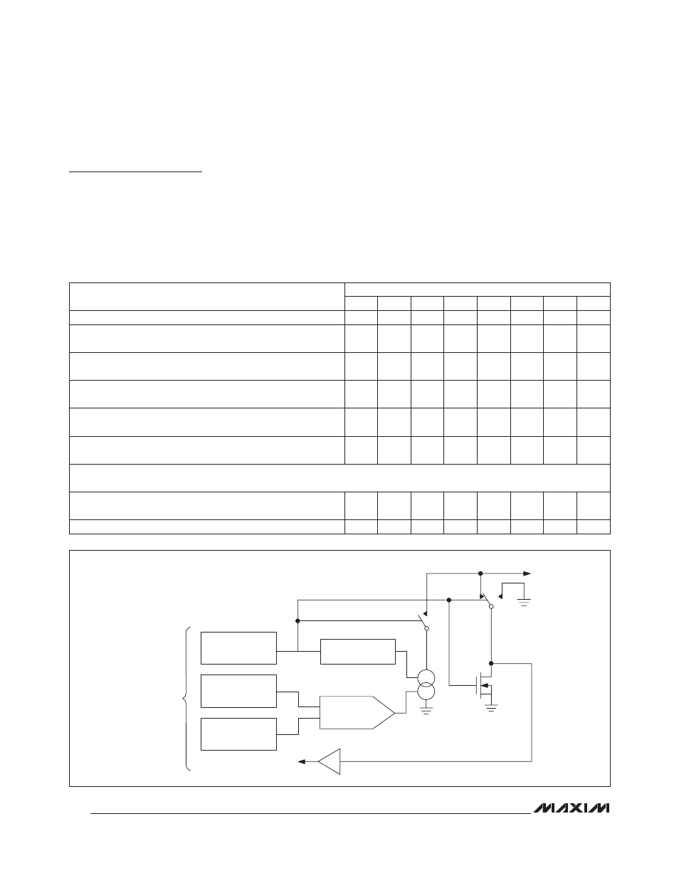
The MAX6948B contains five I/O ports (P0–P4). Configure
the five I/O ports as logic inputs, open-drain logic outputs,
or constant-current sinks in any combination. Table 7
provides a detailed description of the individual port con-
figuration registers. Use registers 0x00 to 0x04 to individu-
ally assign each port (see the PWM Intensity Control and
Phasing section). Use registers 0x0A, 0x0B, and 0x0C to
assign the same port setting to multiple ports (Table 1).
When powered off, the I/O ports remain in high impedance.
Figure 1 shows the I/O port structure of the MAX6948B.
I/O ports P0–P4 default to high impedance on power-up,
to prevent connected ports from drawing current. Ports
used as inputs do not load their source signals.
Table 7. Port Registers Format (0x00 to 0x04, 0x0A, 0x0B, and 0x0C)
Figure 1. Simplified Schematic of I/O Ports
REGISTER DESCRIPTION
REGISTER DATA
D7
D6
D5
D4
D3
D2
D1
D0
Port is logic-low. Port is still active in shutdown mode.
0
0
0
0
0
0
0
0
Port is logic-high. Set this mode when using GPIO as an input.
Port is still active when in shutdown mode.
0
0
0
0
0
0
0
1
Port is a static constant-current sink. Port is high impedance
when in shutdown mode.
0
0
0
0
0
0
1
0
Port is a constant-current sink with a 3/256 duty cycle. Port is
high impedance when in shutdown mode.
0
0
0
0
0
0
1
1
Port is a constant-current sink with a 4/256 duty cycle. Port is
high impedance when in shutdown mode.
0
0
0
0
0
1
0
0
Port is a constant-current sink with a 5/256 duty cycle. Port is
high impedance when in shutdown mode.
0
0
0
0
0
1
0
1
U
U
U
Port is a constant-current sink with a 254/256 duty cycle. Port is
high impedance when in shutdown mode.
1
1
1
1
1
1
1
0
Power-up default setting (port is high impedance)
1
1
1
1
1
1
1
1
8-BIT LATCH
OUTPUT PORT
REGISTER
PWM
GENERATOR
1-BIT LATCH
OUTPUT-CURRENT
REGISTER
4-BIT DAC
3-BIT LATCH
GLOBAL-CURRENT
REGISTER
READ I/O
PORT COMMAND
TO/FROM
SERIAL
INTERFACE
MSB
ENABLE
A
B
n-CHANNEL
MOSFET
I/O PORT
ENABLE = 0x00
SET
CURRENT
POSITION A: 0x00 TO 0x01
POSITION B: 0x02 TO 0xFF
CLOSE SWITCH: 0x02 TO 0xFE