Max6948b, Initial power-up – Rainbow Electronics MAX6948B User Manual
Page 11
High-Efficiency PWM LED Driver with Boost
Converter and Five Constant-Current GPIO Ports
11
MAX6948B
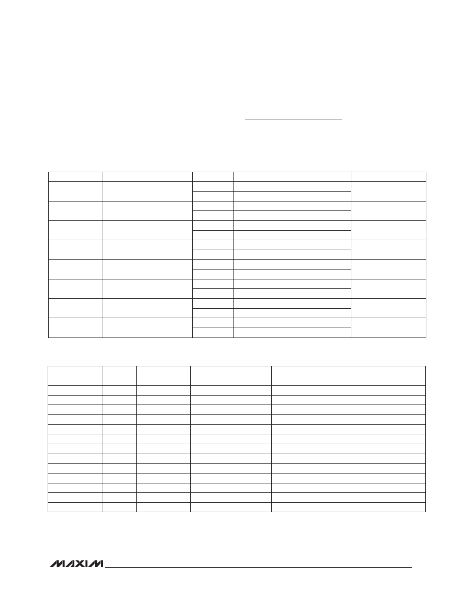
Configuration Register Format (0x10)
Use the configuration register to select PWM phasing
between outputs, monitor fade status, enable hardware
startup from shutdown, and select shutdown or run mode
(Table 2).
Initial Power-Up
On power-up, all control registers are set to power-
up values and the MAX6948B is in shutdown mode
(Table 3).
Table 2. Configuration Register Format (0x10)
Table 3. Power-On Reset (POR) Values
REGISTER BIT
DESCRIPTION
VALUE
FUNCTION
DEFAULT VALUE
D7
Half-/full-boost current
1
Half-boost current set by R
FB
1
0
Full-boost current set by R
FB
D6
Reset/POR option
0
RST does not change register data
0
1
RST resets registers to POR values
D5
PWM stagger
0
PWM outputs are in phase
0
1
PWM outputs are staggered
D4
Hold-off status
0
Device is not in hold-off
Read only
1
Device is in hold-off
D3
Ramp-down (fade-off) status
0
Device is not in fade-off
Read only
1
Device is in fade-off
D2
Ramp-up status
0
Device is not in ramp-up
Read only
1
Device is in ramp-up
D1
Reset-run enable
0
Reset run disabled
0
1
Reset run enabled
D0
Run
0
Shutdown mode
0
1
Run mode
ADDRESS
CODE (hex)
READ/
WRITE
POWER-UP
VALUE (hex)
REGISTER FUNCTION
POR DESCRIPTION
0x00
R/W
0xFF
P0
Port P0 high impedance
0x01
R/W
0xFF
P1
Port P1 high impedance
0x02
R/W
0xFF
P2
Port P2 high impedance
0x03
R/W
0xFF
P3
Port P3 high impedance
0x04
R/W
0xFF
P4
Port P4 high impedance
0x10
R/W
0x00
Configuration
Shutdown mode (reset run disabled)
0x11
R/W
0x00
Ramp-down
Port ramp-down and hold-off disabled
0x12
R/W
0x00
Ramp-up
Port ramp-up disabled
0x13
R/W
0x03
Output current
P0, P1 at full current; P2, P3, P4 at half current
0x15
R/W
0x07
Global current
Maximum output current
0x20
R/W
0x00
Boost PWM (MSB)
Zero PWM duty cycle
0x21
R/W
0x00
Boost PWM (LSB)
Zero PWM duty cycle
0x22
R/W
0x01
Boost status
Boost circuit in standby mode