Max6948b – Rainbow Electronics MAX6948B User Manual
Page 26
High-Efficiency PWM LED Driver with Boost
Converter and Five Constant-Current GPIO Ports
26
MAX6948B
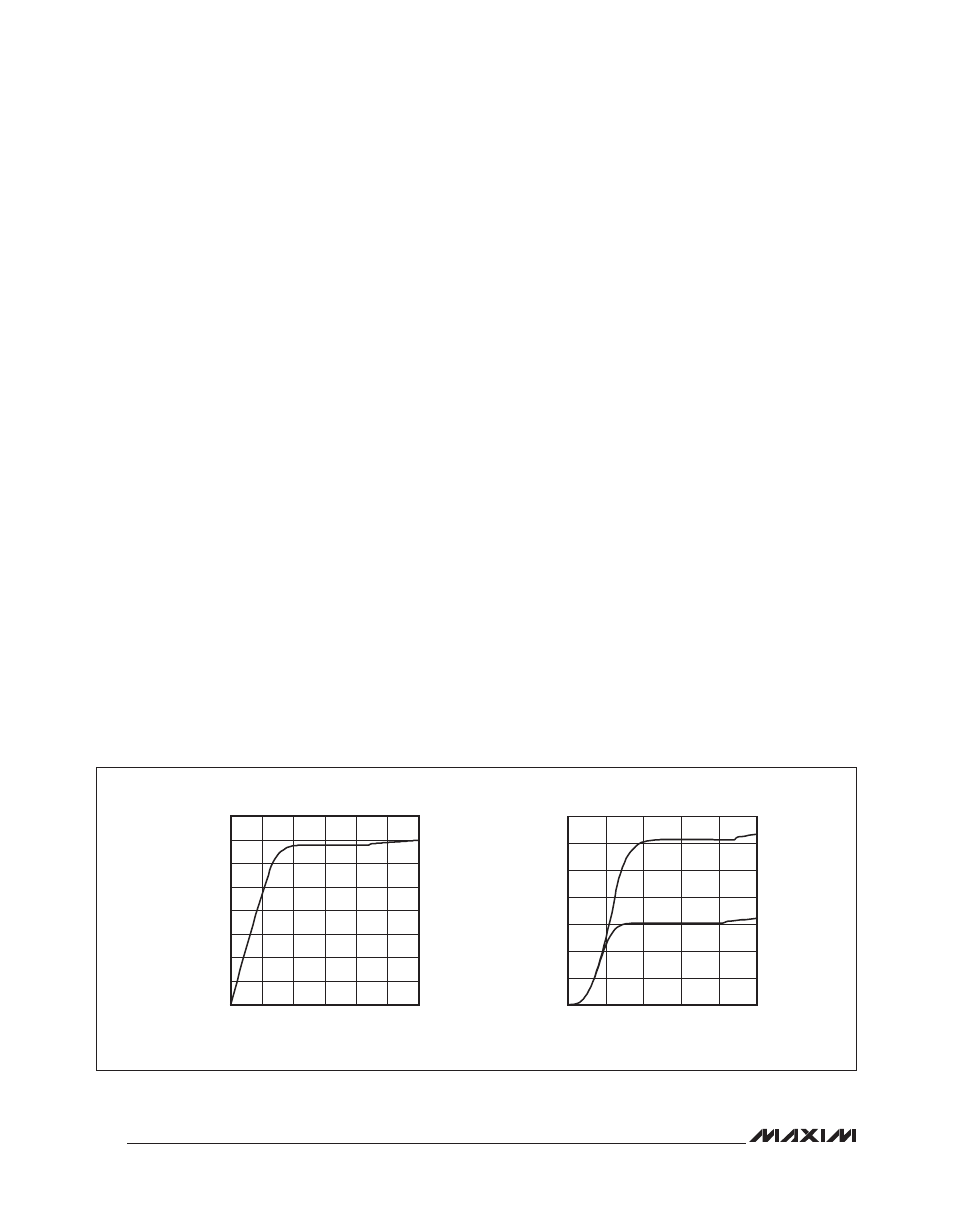
Figure 16. LED Brownout
Driving LEDs into Brownout
The MAX6948B correctly regulates the constant-current
outputs, provided there is a minimum voltage drop
across the port output. This port output voltage is the dif-
ference between the load (typically LED) supply and the
load voltage drop (LED forward voltage). If the LED sup-
ply drops so that the minimum port output voltage is not
maintained, the driver output stages brownout and the
load current falls. The minimum port voltage is approxi-
mately 0.25V at 15mA sink current and approximately
0.3V at 30mA sink current (ports P0, P1) and 0.39V at
5mA sink current and approximately 0.4V at 10mA sink
current (ports P2, P3, P4).
Operating the LEDs directly from a battery supply can
cause brownouts. For example, the LED supply voltage
is a single rechargeable lithium-ion battery with a maxi-
mum terminal voltage of 4.2V on charge, 3.4V to 3.7V
most of the time, and down to 3V when discharged. In
this scenario, the LED supply falls significantly below the
brownout point when the battery is at end-of-life voltage (3V).
Figure 16 shows the typical current sink by a King Bright
AA3020ARWC/A white LED as the LED supply voltage is
varied from 2.5V to 5.5V. The LED currents shown are for
ports programmed for 10mA and 30mA constant current,
swept over a 2.5V to 5.5V LED supply voltage range.
It can be seen that the LED forward voltage falls with
current, allowing the LED current to fall gracefully, not
abruptly, in brownout. In practice, the LED current drops
to 11mA to 12.5mA at a 3V LED supply voltage; this is
acceptable performance at end-of-life in many backlight
applications.
Output-Level Translation
The open-drain output architecture allows the ports to level
translate the outputs to higher or lower voltages than the
MAX6948B supply (V
DD
). Use an external pullup resistor on
any output to convert the high-impedance, logic-high condi-
tion to a positive voltage level. Connect the resistor to any
voltage up to 5.5V. When using a pullup on a constant-cur-
rent output, select the resistor value to sink no more than
a few hundred FA in logic-low condition. This ensures
that the current-sink output saturates close to GND.
For interfacing CMOS inputs, a pullup resistor value of
220kI is a good starting point. Use a lower resistance
to improve noise immunity in applications where power
consumption is less critical, or where a faster rise time is
needed for a given capacitive load.
Using Stagger with Fewer Ports
The stagger option, when selected, applies to all ports
configured as constant-current outputs. The PWM cycles
are separated to six evenly spaced start positions
(Figure 3). Optimize phasing when using some of the
ports as constant-current outputs by allocating the ports
with the most appropriate start positions. In general,
choose the ports that spread the PWM start positions as
evenly as possible. This optimally spreads out the cur-
rent demand from the ports’ load supply.
Generating a Shutdown/Run Output
4.5
4.0
3.5
3.0
5
10
15
20
25
30
35
0
2.5
5.0
I
LED
vs. V
LED
SUPPLY
V
LED
SUPPLY (V)
I
LED
(mA)
V
LED
vs. V
LED
SUPPLY
V
LED
SUPPLY (V)
V
LED
(V)
5.0
4.5
3.0
3.5
4.0
2.6
2.7
2.8
2.9
3.0
3.1
3.2
3.3
2.5
2.5
5.5