Max6948b, Message format for writing the led driver, Message format for reading – Rainbow Electronics MAX6948B User Manual
Page 24
High-Efficiency PWM LED Driver with Boost
Converter and Five Constant-Current GPIO Ports
24
MAX6948B
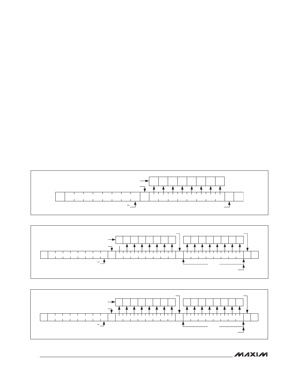
Figure 13. Command Byte Received
Figure 14. Command and Single Data Byte Received
Figure 15. N Data Bytes Received
Message Format for Writing the LED Driver
A write to the MAX6948B comprises the transmission of
the slave address with the R/W bit set to zero, followed
by at least 1 byte of information. The first byte of infor-
mation is the command byte. The command byte deter-
mines which register of the MAX6948B is to be written by
the next byte, if received. If a STOP condition is detected
after the command byte is received, the MAX6948B
takes no further action (Figure 13) beyond storing the
command byte.
Any bytes received after the command byte are data
bytes. The first data byte goes into the internal regis-
ter of the MAX6948B selected by the command byte
(Figure 14).
If multiple data bytes are transmitted before a STOP
condition is detected, these bytes are generally stored
in subsequent MAX6948B internal registers because
the command-byte address generally autoincrements
(Table 1).
Message Format for Reading
The MAX6948B is read using the MAX6948B’s internally
stored command byte as an address pointer, the same
way the stored command byte is used as an address
pointer for a write. The pointer generally autoincrements
after each data byte is read using the same rules as for
a write (Table 1). Thus, a read is initiated by first config-
uring the MAX6948B’s command byte by performing a
write (Figure 13). The master can now read n consecu-
tive bytes from the MAX6948B, with the first data byte
being read from the register addressed by the initialized
command byte. When performing read-after-write verifi-
cation, remember to reset the command byte’s address
because the stored command-byte address is generally
autoincremented after the write (Figure 15, Table 1).
S
A
A
P
0
SLAVE ADDRESS
COMMAND BYTE
ACKNOWLEDGE FROM MAX6948B
D15
D14
D13
D12
D11
D10
D9
D8
COMMAND BYTE IS STORED ON RECEIPT OF
STOP CONDITION
ACKNOWLEDGE FROM MAX6948B
R/W
S
A
A
A
P
0
SLAVE ADDRESS
COMMAND BYTE
DATA BYTE
1
BYTE
AUTOINCREMENT MEMORY ADDRESS
D15 D14 D13 D12 D11 D10 D9
D8
D1
D0
D3
D2
D5
D4
D7
D6
ACKNOWLEDGE FROM MAX6948B
ACKNOWLEDGE FROM MAX6948B
ACKNOWLEDGE FROM MAX6948B
HOW COMMAND BYTE AND DATA BYTE MAP INTO
MAX6948B REGISTERS
R/W
S
A
A
A
P
0
SLAVE ADDRESS
COMMAND BYTE
DATA BYTE
N
BYTES
D15 D14 D13 D12 D11 D10 D9
D8
D1
D0
D3
D2
D5
D4
D7
D6
ACKNOWLEDGE FROM MAX6948B
ACKNOWLEDGE FROM MAX6948B
ACKNOWLEDGE FROM MAX6948B
HOW COMMAND BYTE AND DATA BYTE MAP INTO
MAX6948B REGISTERS
R/W
AUTOINCREMENT MEMORY ADDRESS