Max6948b, Table 14. recommended inductors, Applications information – Rainbow Electronics MAX6948B User Manual
Page 25
High-Efficiency PWM LED Driver with Boost
Converter and Five Constant-Current GPIO Ports
25
MAX6948B
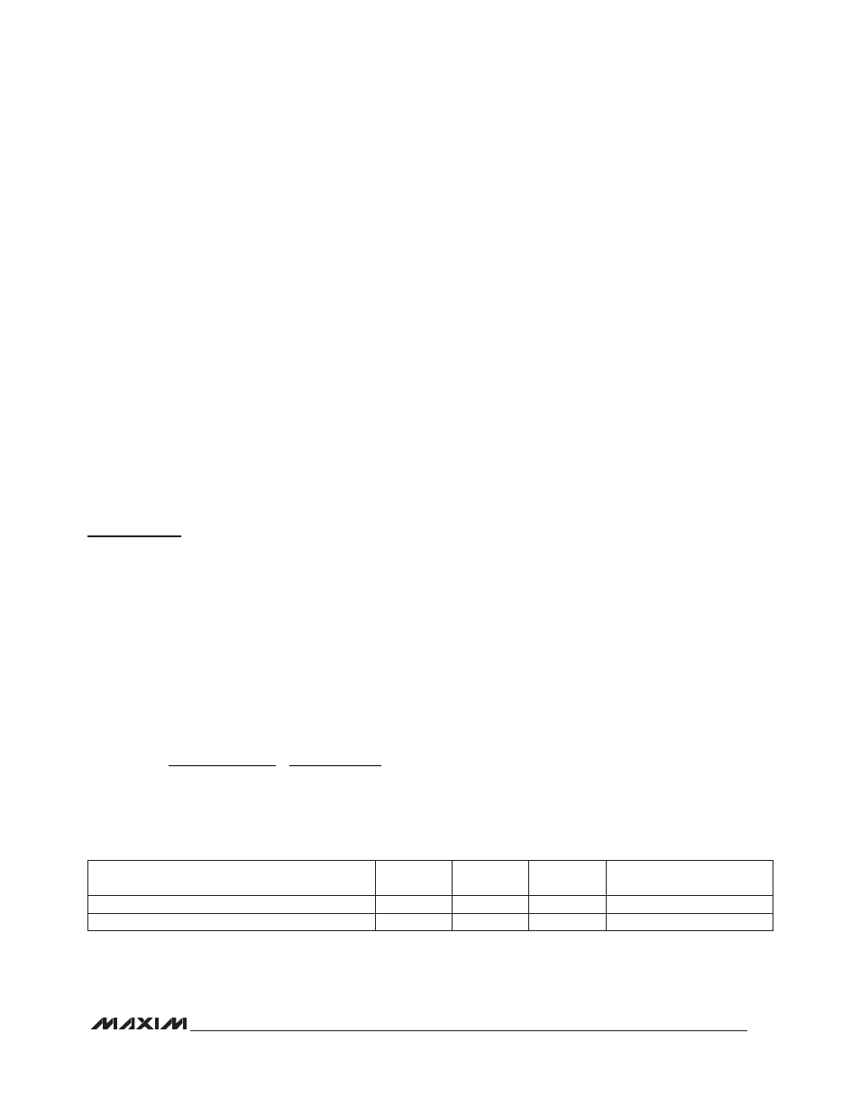
Table 14. Recommended Inductors
Operation with Multiple Masters
When the MAX6948B is operated on a 2-wire interface
with multiple masters, a master reading the MAX6948B
uses a repeated start between the write that sets the
MAX6948B’s address pointer, and the read(s) that takes
the data from the location(s). This is because it is pos-
sible for master 2 to take over the bus after master 1 has
set up the MAX6948B’s address pointer but before mas-
ter 1 has read the data. If master 2 subsequently resets
the MAX6948B’s address pointer, master 1’s read can
be from an unexpected location.
Command Address Autoincrementing
Address autoincrementing allows the MAX6948B to be
configured with fewer transmissions by minimizing the
number of times the command address needs to be
sent. The command address stored in the MAX6948B
generally increments after each data byte is written or
read (Table 1). Autoincrement only works when doing a
burst read or write.
Applications Information
Inductor Selection
The MAX6948B is optimized for a 10FH inductor,
although larger or smaller inductors can be used. Using
a smaller inductor results in discontinuous-current-mode
operation over a larger range of output power, whereas
use of a larger inductor results in continuous conduction
for most of the operating range.
To prevent core saturation, ensure that the inductor’s
saturation current rating exceeds the peak inductor cur-
rent for the application. For larger inductor values and
continuous conduction operation, calculate the worst-
case peak inductor current with the following formula:
OUT
OUT(MAX)
IN(MIN)
PEAK
IN(MAX)
V
I
V
0.5 s
I
0.9 V
2 L
Ч
Ч
µ
=
+
Ч
Ч
Otherwise, for small values of L in discontinuous conduc-
tion operation, I
PEAK
is 860mA (typ). Table 14 provides a
list of recommended inductors.
Capacitor Selection
The typical input capacitor value is 2.2FF and the typical
output capacitor is 0.22FF. Higher value capacitors can
reduce input and output ripple, but at the expense of size
and higher cost. For best operation, use ceramic X5R or
X7R dielectric capacitors. Generally, ceramic capacitors
with smaller case sizes have poorer DC bias character-
istics than larger case sizes for a certain capacitance
value. Select the capacitor that yields the best trade-off
between case size and DC bias characteristics.
Diode Selection
The high switching frequency of the MAX6948B demands
a high-speed rectification diode for optimum efficiency.
A Schottky diode is recommended due to its fast recov-
ery time and low forward-voltage drop. Ensure that the
diode’s average and peak current rating exceeds the
average output current and peak inductor current. In
addition, the diode’s reverse-breakdown voltage must
exceed V
OUT
.
Compensation Network Selection
The step-up converter uses an external compensation
network from COMP to GND to ensure stability. For 5 or 6
WLEDs, choose C
COMP
= C
OUT
/10 for optimal transient
response.
Port Input and I
2
C Interface Logic Voltages
The MAX6948B I
2
C supply (V
DD
) accepts voltages
from 1.7V up to the boost-converter input (V+). V
DD
determines the I
2
C interface (SDA, SCL), I
2
C slave-
address select input (AD0), and reset input (RST) logic
voltages. The five I/O ports P0–P4 are overvoltage pro-
tected to 5.5V independent of V
DD
or V+. This allows the
MAX6948B to operate from one supply voltage, such as
3.3V, while driving some of the five I/Os as inputs from a
different logic level, such as 5V.
VENDOR PART NUMBER
L
(µH)
DCR
(mω)
I
SAT
(A)
CASE SIZE
(mm)
TOKO 1069AS-220M
22
570
0.47
3 x 3 x 1.8
TOKO 1098AS-100M
10
290
0.75
2.8 x 3 x 1.2