Max6948b – Rainbow Electronics MAX6948B User Manual
Page 17
High-Efficiency PWM LED Driver with Boost
Converter and Five Constant-Current GPIO Ports
17
MAX6948B
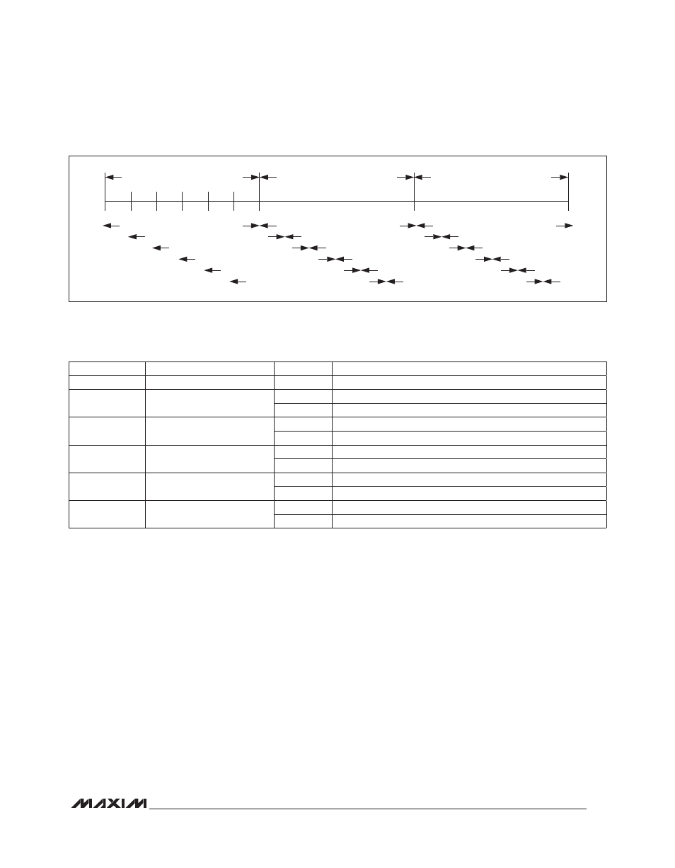
Figure 3. Staggered Port and Boost PWM Waveform
Ports Configured as Inputs
Configure a port as a logic input by writing 0x01 to the
port’s output register (Table 7). Reading an input port
register returns the logic levels from the I/O ports config-
ured as a logic input (Table 10). The input port register
returns logic 0 in the appropriate bit position for a port
not configured as a logic input. The input ports’ registers
are read only. The MAX6948B ignores writes to the input
ports register.
Standby Mode and Operating Current
Configuring all the ports as logic inputs or outputs (all
output registers set to value 0x00 or 0x01) or high imped-
ance (output register set to value 0xFF) puts the device
into standby mode. Put the MAX6948B into standby
mode for lowest supply current consumption.
Setting a port as a constant-current output increases the
operating current (output register set to a value between
0x02 and 0xFE), even if a load is not applied to the
port. The MAX6948B enables an internal current mirror
to provide the accurate constant-current sink. Enabling
the internal current mirror increases the device’s supply
current. Each output contains a gated mirror, which acti-
vates only when required.
In PWM mode, the current mirror turns on only for the
duration of the output’s on-time. This means that the
operating current varies as constant-current outputs are
turned on and off through the serial interface, as well as
by the PWM intensity control.
Table 10. Input Ports Register Format (0x0E, Read Only)
8.192ms NOMINAL PORT PWM PERIOD
PORT 0 OR PORTS AND BOOST IN PHASE
PORT 2 STAGGERED PWM PERIOD
PORT 3 STAGGERED PWM PERIOD
PORT 1 STAGGERED PWM PERIOD
PORT 4 STAGGERED PWM PERIOD
BOOST STAGGERED PWM PERIOD
42
84
126
168
210
256
NEXT PORT PWM PERIOD
NEXT PORT PWM PERIOD
PORT 0 OR PORTS AND BOOST IN PHASE
PORT 2 STAGGERED PWM PERIOD
PORT 3 STAGGERED PWM PERIOD
PORT 1 STAGGERED PWM PERIOD
PORT 4 STAGGERED PWM PERIOD
BOOST STAGGERED PWM PERIOD
PORT 0 OR PORTS AND BOOST IN PHASE
PORT 2 STAGGERED PWM PERIOD
REGISTER BIT
DESCRIPTION
VALUE
FUNCTION
D7, D6, D5
Reserved
0
—
D4
P4
0
Port P4 is logic input low, or is not set as an input
1
Port P4 is logic input high
D3
P3
0
Port P3 is logic input low, or is not set as an input
1
Port P3 is logic input high
D2
P2
0
Port P2 is logic input low, or is not set as an input
1
Port P2 is logic input high
D1
P1
0
Port P1 is logic input low, or is not set as an input
1
Port P1 is logic input high
D0
P0
0
Port P0 is logic input low, or is not set as an input
1
Port P0 is logic input high