Absolute maximum ratings, General electrical characteristics – Rainbow Electronics MAX8982X User Manual
Page 7
Power-Management ICs for
ICERA E400/E450 Platform
MAX8982A/MAX8982X
7
Stresses beyond those listed under “Absolute Maximum Ratings” may cause permanent damage to the device. These are stress ratings only, and functional
operation of the device at these or any other conditions beyond those indicated in the operational sections of the specifications is not implied. Exposure to absolute
maximum rating conditions for extended periods may affect device reliability.
V
DDA
, V
DDB
, IN4, IN1A, IN1B to GND ....................-0.3V to +6V
REFBP, BUCK1, BUCK2, BUCK3, BUCK4,
EN to GND ...............................-0.3V to (V
IN1A,
V
IN1B
+ 0.3V)
SDA, SCL, PWR_REQ, DVS1, IRQ, RESET, IN3,
N32kHz to GND .............................. -0.3V to (V
BUCK2
+ 0.3V)
OUT1, OUT2 to GND ............................. -0.3V to (V
DDA
+ 0.3V)
OUT3, OUT5, OUT6, VSIM to GND ....... -0.3V to (V
DDB
+ 0.3V)
OUT8 to GND ........................................... -0.3V to (V
IN4
+ 0.3V)
OUT4, OUT9 to GND ............................... -0.3V to (V
IN3
+ 0.3V)
PGND1, PGND2, PGND3, PGND4 to GND .........-0.3V to +0.3V
DR1, DR2, DR3 to GND ..........................-0.3V to (V
IN1_
+ 0.3V)
LX1 Continuous Current (Note 1) ...................................1200mA
LX2, LX3 Continuous Current (Note 1) ............................600mA
LX4 Continuous Current (Note 1) ...................................1800mA
Continuous Power Dissipation (T
A
= +70NC)
7x6 42-Bump WLP, 0.5mm Pitch, 3.75mm x 3.20mm
(derate 27.8mW/NC above +70NC) ................................2.22W
Junction-to-Ambient Thermal Resistance (B
JA
)
(Note 2) ........................................................................36NC/W
Operating Temperature Range .......................... -40NC to +85NC
Junction Temperature .....................................................+150NC
Storage Temperature Range ............................ -65NC to +150NC
Soldering Temperature (reflow) ......................................+260NC
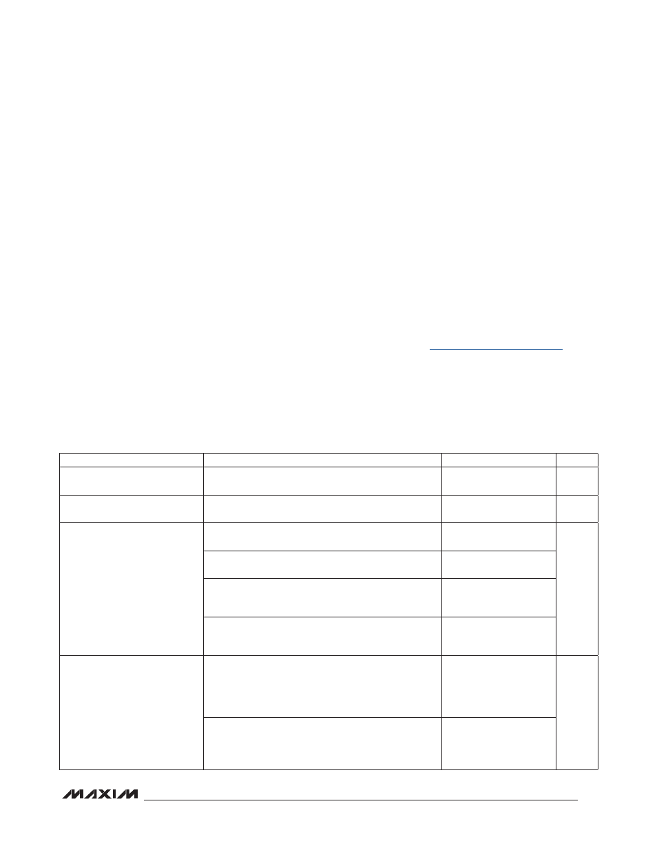
GENERAL ELECTRICAL CHARACTERISTICS
(MAX8982A: V
IN1A
= V
IN1B
= +5.0V and C
OUT1,2,3+CIN_
= 1000FF, MAX8982X: V
IN1A
= V
IN1B
= +3.3V and CO
UT1,2,3+CIN_
= 20FF,
C
REFBP
= 0.1FF, T
A
= -40NC to +85NC. Typical values are at T
A
= +25NC, unless otherwise noted.) (Note 3)
ABSOLUTE MAXIMUM RATINGS
Note 1: LX1–LX4 have internal clamp diodes to PGND_, IN1A, and IN1B. Applications that forward bias this diode should take
care not to exceed the power dissipation limits of the device.
Note 2: Package thermal resistance was obtained using the method described in JEDEC specification JESD51-7, using a four-
layer board. For detailed information on package thermal considerations, refer to
PARAMETER
CONDITIONS
MIN
TYP
MAX
UNITS
IN1A, IN1B, IN4 ESD Protection
Module level ESD protection, in-circuit tested with 0.1FF
ceramic capacitor
Q
10
kV
Shutdown Supply Current
(Note 4)
EN = GND
10
F
A
No Load Supply Current
MAX8982A, V
EN
= V
IN1_
, BUCK3 and OUT3 on (default
output), all other regulators off
300
F
A
MAX8982X, V
EN
= V
IN1_
, OUT3 on (default output), all
other regulators off
300
MAX8982A, V
EN
= V
IN1_
, BUCK1 on (default output),
BUCK2 on (default output), BUCK3 on (default output),
all LDOs (except LDO8) default output ON
600
MAX8982X, V
EN
= V
IN1_
, BUCK1 on (default output),
BUCK2 on (default output), all LDOs (except LDO8)
default output ON
600
Loaded Supply Current
MAX8982A, V
EN
= V
IN1_
, 32kHz clock on, BUCK2 on
(default output) with 200FA load, BUCK3 on (default
output), OUT3 on (default output) with 20FA load, OUT2
on (default output) with 100FA load, V
VSIM
= 3.0V with
50FA load, OUT8 on (default output) with 100FA load
1000
F
A
MAX8982X, V
EN
= V
IN1_
, 32kHz clock on, BUCK2 on
(default output) with 200FA load, OUT3 on (default
output) with 20FA load, OUT2 on (default output) with
100FA load, V
VSIM
= 3.0V with 50FA load
1000