Figure 9. por state diagram, Figure 11. flash timing diagram, Current regulators (dr1, dr2, dr3) – Rainbow Electronics MAX8982X User Manual
Page 39: Embedded flash timer, Irq description, Description
Power-Management ICs for
ICERA E400/E450 Platform
MAX8982A/MAX8982X
39
Current Regulators (DR1, DR2, DR3)
The ICs have three current regulators that can handle
up to 24mA. The sink current for each current regulator
is set from 3mA to 24mA in 3mA increments through I
2
C.
The default set current is 24mA on each channel.
If a current other than the programmable options is
required, a series resistor can be added to set a current
from 0mA to 24mA (Figure 10). The resistor forces the
current regulator to operate in dropout. Set the resistor
value to (V
IN1_
- V
F
)/I
LED
, where V
F
is the forward volt-
age of the LED at the desired current and I
LED
is the
desired LED current. I
LED
must be less than the pro-
grammed current (24mA default).
Each current regulator has an embedded flash timer.
The flash time is programmable through the I
2
C inter-
face. This feature allows the system designer to generate
a desired pattern on LED.
Embedded Flash Timer
The flash generator is clocked by the internal 32kHz oscil-
lator. It consists of a counter that wraps at a programmable
value to provide a configurable sequence period (t
P
). Up
to four on-pulses can be programmed in this sequence
and the start time for each pulse is programmed indi-
vidually (t
1
–t
4
). The programmable LED on-time (t
ON
)
for each pulse is the same for each pulse. The flash tim-
ing is shown in Figure 11. The dimming current can be
changed at any time.
IRQ Description
The ICs use the IRQ to indicate to the baseband pro-
cessor that their status has changed. The IRQ signal is
asserted (pulls low) whenever an interrupt is triggered.
The baseband controller shall read the interrupt register
to find sources of interrupt. IRQ is cleared (high) as soon
as the read sequence of the last IRQ register that con-
tains an active interrupt starts. If an interrupt is captured
during the read sequence, IRQ becomes active (low)
after minimum 24 cycles of the I
2
C clock. An interrupt
can be masked to prevent IRQ from being asserted for
the masked event. A mask bit in the IRQM register imple-
ments masking.
For UVLO interrupt bit, the bit status is only maintained
as long as V
BUS
is higher than 2.0V in any conditions.
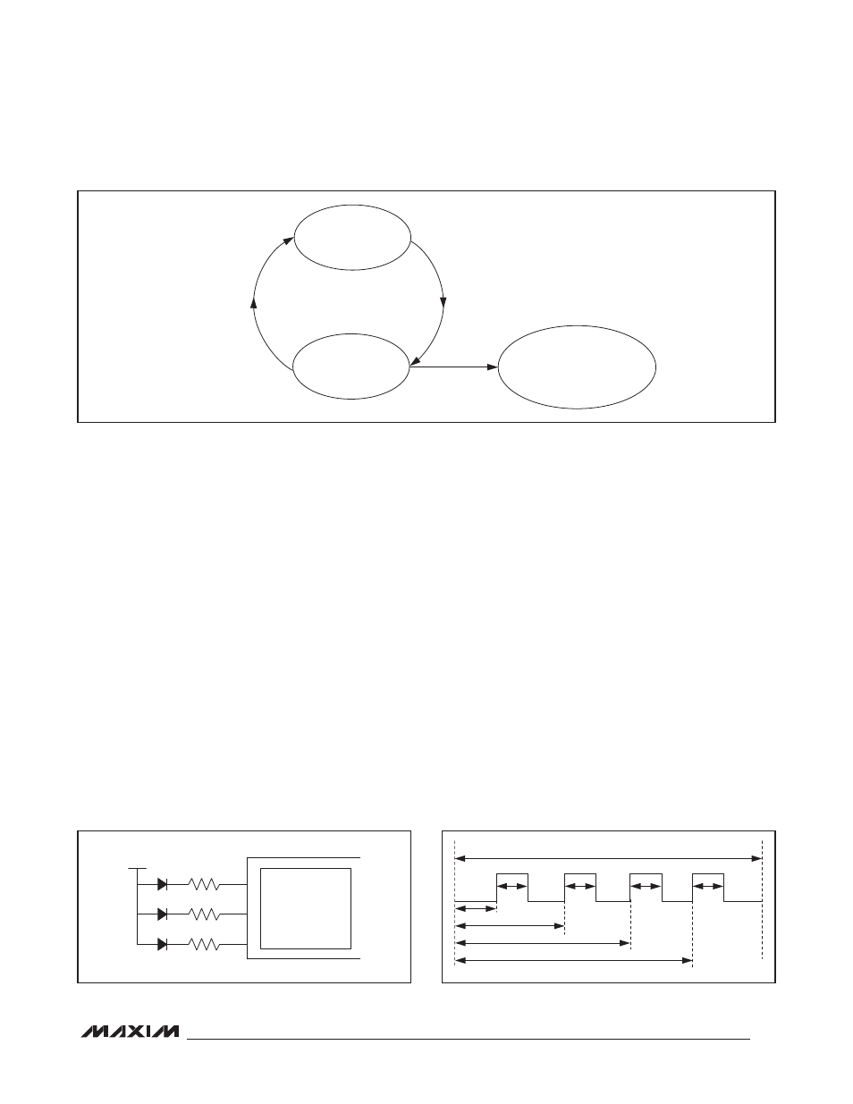
Figure 9. POR State Diagram
Figure 10. Adding Series Resistors to Adjust LED Current
Figure 11. Flash Timing Diagram
EN = HIGH
AND
IN1_ VALID
PWR _REQ = LOW
I
2
C ENABLED
POR ON ALL REGISTERS
IN MAX8982A/
MAX8982X
EN = LOW
OR
IN1_ INVALID
THE VALUES IN THE BUCK1DVS1
AND BUCK1DVS2 REGISTERS
ARE RESET TO THEIR DEFAULTS
WHEN PWR_REQ GOES LOW
3-CHANNEL
CURRENT
REGULATOR
(24mA, DEFAULT)
DR 1
V
IN1_
DR 2
DR 3
t
1
t
ON
t
ON
t
P
t
ON
t
ON
t
2
t
3
t
4