Active discharge – Rainbow Electronics MAX8982X User Manual
Page 35
Power-Management ICs for
ICERA E400/E450 Platform
MAX8982A/MAX8982X
35
Active Discharge
All regulators include an internal resistor for discharging
the output when the regulator is shut down. In the default
state (except BUCK2), this resistor is not connected so
the output decay depends only on the applied load. To
enable this discharge resistor, set the appropriate bit in
the BUCK1-4ADIS, LDO1-8ADIS, or LDO9ADIS register.
The active discharge resistor values are specified in the
General Electrical Characteristics table.
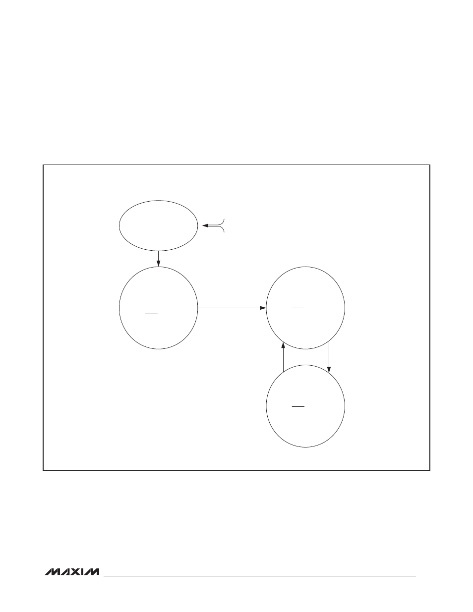
Figure 3. Power-On/Off State Diagram with IN3 Connected to BUCK2 Output and IN4 Connected to IN1_. Default PWR_REQ
Regulators Are Shown.
SHUTDOWN
ALL REGULATORS
DISABLED
I
2
C HIGH IMPEDANCE
REF DISABLED
32kHz DISABLED
BUCK3 ENABLED (MAX8982A)
BUCK2 ENABLED
LDO3 ENABLED
LDO8 ENABLED (MAX8982A)
LDO9 ENABLED
RESET = HIGH
V
REFBP
= 0.8V
I
2
C ENABLED
32kHz CLOCK ENABLED
BUCK1 ENABLED
LDO1 ENABLED
LDO2 ENABLED
LDO4 ENABLED
LDO6 ENABLED
RESET = HIGH
V
REFBP
= 0.8V
I
2
C ENABLE
32kHz CLOCK ENABLED
BUCK1 DISABLED
LDO1 DISABLED
LDO2 DISABLED
LDO4 DISABLED
LDO6 DISABLED
RESET = HIGH
V
REFBP
= 0.8V
I
2
C ENABLED
32kHz CLOCK ENABLED
V
IN1_
< 3.5V (MAX8982A)
OR V
IN1_
< 2.4V (MAX8982X)
OR V
IN1_
> 5.75V
OR EN = LOW
V
IN1_
> 3.8V (TYP) (MAX8982A)
V
IN1_
> 2.7V (TYP) (MAX8982X)
AND EN = HIGH
NOTE: ENABLE OF BUCKS AND
LDOS AND CONTROL OF
BUCKS AND LDOS
BY PWR_REQ
CAN BE MODIFIED
AFTER STARTUP THROUGH I
2
C.
PWR_REQ = HIGH
FROM
ANY STATE
POWER-UP
PWR_REQ
= HIGH
PWR_REQ
= LOW