Table 1. summary of power supplies, Pin description (continued) – Rainbow Electronics MAX8982X User Manual
Page 29
Power-Management ICs for
ICERA E400/E450 Platform
MAX8982A/MAX8982X
29
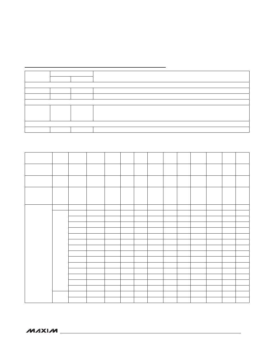
Table 1. Summary of Power Supplies
Pin Description (continued)
*BUCK3, BUCK4, and OUT8 are for the MAX8982A only.
PIN
NAME
FUNCTION
MAX8982A MAX8982X
LOGIC OUTPUTS
C6
IRQ
IRQ
Active-Low, Open-Drain Interrupt Output. Internal pullup resistor, 200kI, to BUCK2.
C3
RESET
RESET
Active-Low, Open-Drain Reset Output. There is an internal 14kI pullup resistor to BUCK2.
REFERENCE OUTPUT
A4
REFBP
REFBP
Reference Bypass. Connect the reference bypass capacitor from REFBP to GND. See
Table 3. High impedance in off condition. V
REFBP
is 0.8V (typ). Do not use to provide
power to external circuitry.
32kHz CLOCK
A1
N32kHz
N32kHz
32kHz Clock Output. This output is supplied from BUCK2.
PARAMETER BUCK1 BUCK2 BUCK3* BUCK4* OUT1 OUT2
OUT3
OUT4 OUT5
OUT6
OUT7
(VSIM)
OUT8* OUT9
Function
Core
System
IO
LDO
INPUT
PA
RF
RF
Analog
PLL
SD
TCXO
SIM
USB
BB
Default
Voltage (V)
0.9
1.8
3.2
3.4
2.7
1.8
2.8
0.9
3.0
2.7
3.00
3.0
0.9
Continuous
Output Current
(mA)
1200
600
600
1800
300
150
150
50
150
150
150
150
50
Programmable
Voltage
Options (V)
0.600
N/A
2.90
3.00
2.65
1.5
2.65
0.8
2.80
2.65
1.80
3.00
0.8
25mV
step
2.95
3.05
2.70
1.8
2.70
0.9
2.90
2.70
3.00
3.10
0.9
3.00
3.10
2.75
2.7
2.75
1.0
3.00
2.75
3.20
1.0
3.05
3.15
2.80
1.7
2.80
1.1
3.20
2.80
3.30
1.1
3.10
3.20
2.85
2.85
1.2
2.85
1.2
3.15
3.25
2.90
2.90
2.90
3.20
3.30
2.95
2.95
2.95
3.25
3.35
3.00
3.00
3.00
3.30
3.40
3.35
3.45
3.40
3.50
3.45
3.55
3.50
3.60
3.55
3.65
3.60
3.70
1.20
3.65
3.75