Figure 12. i2c bit transfer, Figure 13. start and stop conditions, Reset signal to b/b chipset – Rainbow Electronics MAX8982X User Manual
Page 40: I2c serial interface, Bit transfer, Start and stop conditions, Reset, Signal to b/b chipset, C serial interface, Bit transfer start and stop conditions
Power-Management ICs for
ICERA E400/E450 Platform
MAX8982A/MAX8982X
40
RESET SIGNAL to B/B Chipset
The ICs include one dedicated reset output called
RESET. This is the reset signal for the core and RTB
(real-time block) in baseband. RESET goes high after the
ICs’ power-up sequence is complete. RESET is pulled
low when the ICs are shut down (due to input supply out
of range or EN goes low).
I
2
C Serial Interface
An I
2
C-compatible, 2-wire serial interface is used for
regulator on/off control, setting output voltages, LED
control, and other functions. See Table 5 for the com-
plete register map.
The I
2
C serial bus consists of a bidirectional serial-data
line (SDA) and a serial-clock line (SCL). I
2
C is an open-
drain bus. SDA and SCL require pullup resistors (500I
or greater). Optional 24I resistors in series with SDA and
SCL help to protect the device inputs from high-voltage
spikes on the bus lines. Series resistors also minimize
crosstalk and undershoot on bus lines.
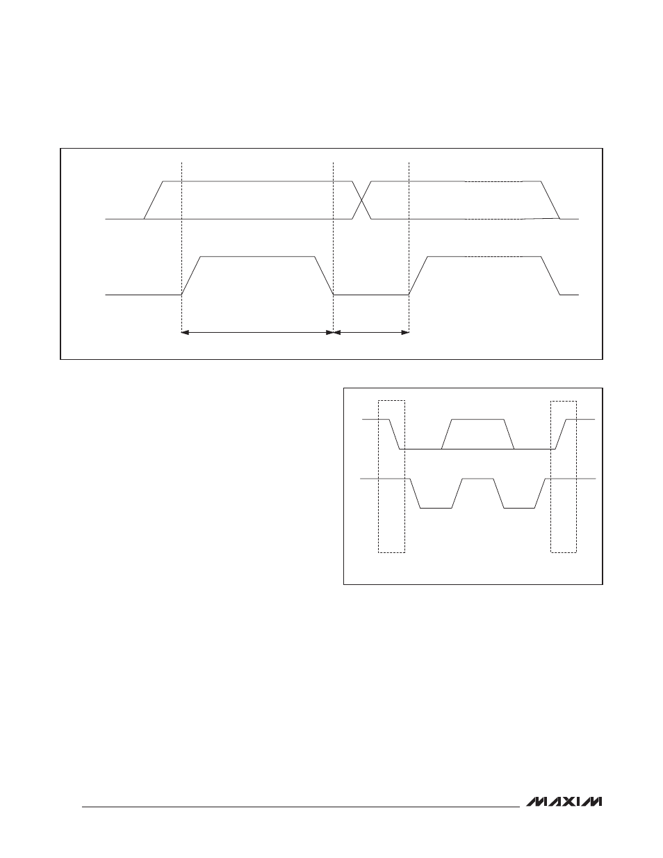
Bit Transfer
One data bit is transferred for each SCL clock cycle. The
data on SDA must remain stable during the high portion of
the SCL clock pulse (Figure 12). Changes in SDA while SCL
is high are control signals (START and STOP conditions).
START and STOP Conditions
Each transmit sequence is framed by a START (S) condi-
tion and a STOP (P) condition. Each packet is 9 bits long; 8
bits of data followed by the acknowledge bit. The ICs sup-
port data transfer rates with a SCL frequency up to 400kHz.
Both SDA and SCL remain high when the bus is not
busy. The master device initiates communication by
issuing a START condition. A START condition is a
high-to-low transition of SDA, while SCL is high. A STOP
condition is a low-to-high transition of the data line while
SCL is high (Figure 13).
A START condition from the master signals the begin-
ning of a transmission to the ICs. The master terminates
transmission by issuing a not acknowledge followed by a
STOP condition. See the Acknowledge section for more
information. The STOP condition frees the bus. To issue
a series of commands to the slave, the master can issue
Figure 12. I
2
C Bit Transfer
Figure 13. START and STOP Conditions
SCL
SDA
DATA LINE STABLE DATA VALID
CHANGE OF DATA ALLOWED
SDA
SCL
START
CONDITION
STOP
CONDITION