Table 2. external component list for figure 1 – Rainbow Electronics MAX8982X User Manual
Page 32
Power-Management ICs for
ICERA E400/E450 Platform
MAX8982A/MAX8982X
32
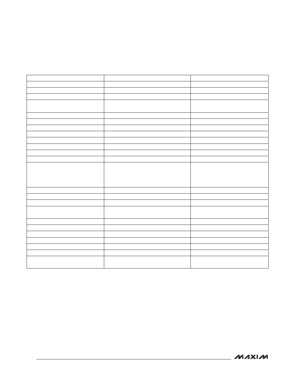
Table 2. External Component List for Figure 1
Note: Input/output capacitance should be as close as possible to the IC. All capacitors are ceramic X5R or X7R, unless otherwise noted.
LOCATION
EXTERNAL COMPONENTS
NOTES
IN1A, IN1B
3 x 330FF tantalum capacitors
Buck stability and GSM PA supply
IN3
2.2FF
Input for LDO4 and LDO9
IN4
1.0FF
Input for LDO8
OUT1
4.7FF
LDO compensation and load transient
response
OUT2
1.0FF
LDO compensation
OUT3
1.0FF
LDO compensation
OUT4
2.2FF
LDO compensation
OUT5
1.0FF
LDO compensation
OUT6
1.0FF
LDO compensation
VSIM (OUT7)
1.0FF
LDO compensation
OUT8
1.0FF
LDO compensation
OUT9
2.2FF
LDO compensation
V
DDA
, V
DDB
Total capacitance R total output capacitance
for LDO1, LDO2, LDO3, LDO5, LDO6, and
VSIM. Use a 10FF capacitor on V
DDA
/V
DDB
as recommended.
All LDOs stability
BUCK1 for BB Core
2.2FF
For low noise, 1.2A continuous load
BUCK2 for BB System IO
2.2FF
For low noise
BUCK3 as LDO Input
2.2FF
For low noise
BUCK4 for GSM PA/UMTS PA
2 x 22FF
Supply for both GSM PA and UMTS PA
LX1
1FH to 4.7FH
2.2FH recommended (Table 60)
LX2
1FH to 4.7FH
1.0FH recommended (Table 60)
LX3
1FH to 4.7FH
2.2FH recommended (Table 60)
LX4
1FH to 4.7FH
2.2FH recommended (Table 60)
REFBP
0.1FF
Noise filter
EN
A pulldown resistor, if necessary.
Any Bump Required to Pass 8kV
Module Level ESD
0.1FF
Absorb ESD energy