Figure 14. master/slave configuration, Figure 15. i2c acknowledge, System configuration – Rainbow Electronics MAX8982X User Manual
Page 41: Acknowledge, System configuration acknowledge, Figure 14. master/slave configuration figure 15. i, C acknowledge
Power-Management ICs for
ICERA E400/E450 Platform
MAX8982A/MAX8982X
41
REPEATED START (Sr) commands instead of a STOP
command to maintain control of the bus. In general, a
REPEATED START command is functionally equivalent
to a regular START command.
When a STOP condition or incorrect address is detected,
the ICs internally disconnect SCL from the serial inter-
face until the next START condition, minimizing digital
noise and feedthrough.
System Configuration
A device on the I
2
C bus that generates a message is
called a transmitter, and a device that receives the mes-
sage is a receiver. The device that controls the message
is the master, and the devices that are controlled by the
master are called slaves (Figure 14).
The ICs are slave transmitter/receiver devices, and the
B/B chipset is a master transmitter/receiver. The master
initiates data transfer on the bus and generates SCL to
permit data transfer.
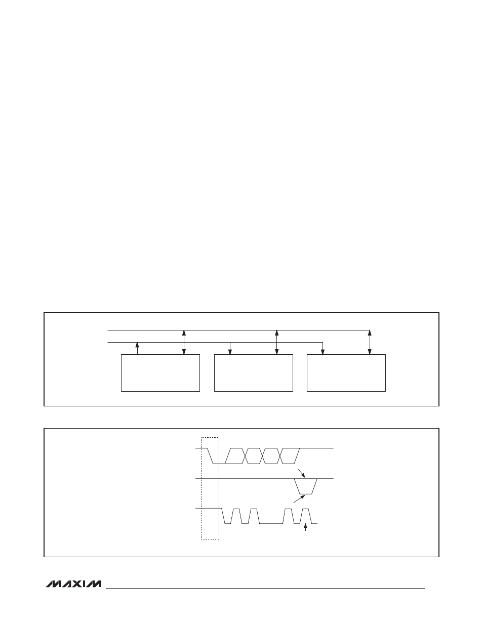
Acknowledge
The number of data bytes between the START and STOP
conditions for the transmitter and receiver are unlimited.
Each 8-bit byte is followed by an acknowledge bit. The
acknowledge bit is a high-level signal put on SDA by the
transmitter during which time the master generates an
extra acknowledge-related clock pulse. A slave receiver
that is addressed must generate an acknowledge after
each byte it receives. Also, a master receiver must
generate an acknowledge after each byte it receives
that has been clocked out of the slave transmitter. See
Figure 15.
The device that acknowledges must pull down the DATA
line during the acknowledge clock pulse, so that the
DATA line is stable low during the high period of the
acknowledge clock pulse (setup and hold times must
also be met). A master receiver must signal an end of
data to the transmitter by not generating an acknowl-
edge on the last byte that has been clocked out of the
slave. In this case, the transmitter must leave SDA high
to enable the master to generate a STOP condition.
Figure 14. Master/Slave Configuration
Figure 15. I
2
C Acknowledge
MASTER
TRANSMITTER/RECEIVER
SLAVE RECEIVER
SLAVE
TRANSMITTER/RECEIVER
SDA
SCL
SDA OUTPUT
FROM TRANSMITTER
SDA OUTPUT
FROM RECEIVER
SCL FROM
MASTER
1
2
8
9
ACKNOWLEDGE
CLOCK PULSE FOR
ACKNOWLEDGEMENT
D7
D6
D0
START CONDITION
NOT ACKNOWLEDGE