Pin description (continued) – Rainbow Electronics MAX8982X User Manual
Page 28
Power-Management ICs for
ICERA E400/E450 Platform
MAX8982A/MAX8982X
28
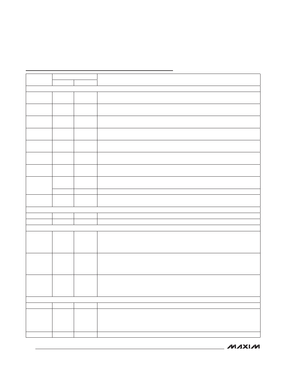
Pin Description (continued)
PIN
NAME
FUNCTION
MAX8982A MAX8982X
LDO REGULATORS
C7
OUT1
OUT1
LDO1 Output. Bypass OUT1 with a 4.7FF ceramic capacitor. OUT1 supplies loads up to
300mA. The default output voltage is 2.7V.
A7
OUT2
OUT2
LDO2 Output. Bypass OUT2 with a 1FF ceramic capacitor. OUT2 supplies loads up to
150mA. The default output voltage is 1.8V.
A6
OUT3
OUT3
LDO3 Output. Bypass OUT3 with a 1FF ceramic capacitor. OUT3 supplies loads up to
150mA. The default output voltage is 2.8V.
B1
OUT4
OUT4
LDO4 Output. Bypass OUT4 with a 2.2FF ceramic capacitor. OUT4 supplies loads up to
50mA. The default output voltage is 0.9V.
C4
OUT5
OUT5
LDO5 Output. Bypass OUT5 with a 1FF ceramic capacitor. OUT5 supplies loads up to
150mA. The default output voltage is 3.0V.
A5
OUT6
OUT6
LDO6 Output. Bypass OUT6 with a 1FF ceramic capacitor. OUT6 supplies loads up to
150mA. The default output voltage is 2.7V.
B5
VSIM
VSIM
LDO7 Output. Bypass VSIM with a 1FF ceramic capacitor. VSIM supplies loads up to
150mA. The default output voltage is 3V.
B4
OUT8
—
LDO8 Output. Bypass OUT8 with a 1FF ceramic capacitor. OUT8 supplies loads up to
150mA. The default output voltage is 3V.
—
DNC
Do Not Connect
A2
OUT9
OUT9
LDO9 Output. Bypass OUT9 with a 2.2FF ceramic capacitor. OUT9 supplies loads up to
50mA. The default output voltage is 0.9V.
I
2
C INTERFACE
D4
SDA
SDA
I
2
C Data. SDA is high impedance when off.
C5
SCL
SCL
I
2
C Clock. SCL is high impedance when off.
CURRENT REGULATORS
B2
DR1
DR1
Current Regulated Driver 1. Typically used to drive an LED. DR1 can be programmed to
sink 3mA to 24mA in 8 steps (24mA default). If the flash timer is activated, the LED can
be programmed to turn on/off in a preprogrammed pattern. See the Embedded Flash
Timer section.
B3
DR2
DR2
Current Regulated Driver 2. Typically used to drive an LED. DR2 can be programmed to
sink 3mA to 24mA in 8 steps (24mA default). If the flash timer is activated, the LED can
be programmed to turn on/off in a preprogrammed pattern. See the Embedded Flash
Timer section.
C2
DR3
DR3
Current Regulated Driver 3. Typically used to drive an LED. DR3 can be programmed to
sink 3mA to 24mA in 8 steps (24mA default). If the flash timer is activated, the LED can
be programmed to turn on/off in a preprogrammed pattern. See the Embedded Flash
Timer section.
LOGIC INPUTS
E3
EN
EN
Active-High IC Enable Input
D5
PWR_REQ PWR_REQ
Active-High to Enable All Designated Step-Down Regulators and LDOs in Sequence.
Active-high/low to enable/disable all step-down converters and LDOs after power-on. The
values in the BUCK1DVS1 and BUCK1DVS2 registers are reset to their defaults when
PWR_REQ goes low in normal operation.
D3
DVS1
DVS1
BUCK1 Output Selection Input for DVS Function