Rainbow Electronics MAX7058 User Manual
Page 9
Operating Mode
TOGGLE and FSEL are two pins available for control-
ling the state of the toggle mode and the operating fre-
quency. The following truth table defines the pin logic
for the four possible operating states.
The internal variable shunt capacitor control pins
(CAP1–CAP4) are used whenever the frequency setting
is 315MHz, in either continuous (TOGGLE = 0, FSEL =
1) or toggle (TOGGLE = 1) mode.
Toggle Definition
With TOGGLE/FSEL set to state 10, the MAX7058 is in
5-packet toggle mode; with TOGGLE/FSEL set to state
11, the MAX7058 is in 100-packet toggle mode. Upon
power-up, the MAX7058 begins transmission at
315MHz within 250µs. Packet termination is defined as
the time duration of greater than 2
18
crystal oscillator ref-
erence clock cycles (17.49ms) with DIN continuously at
logic 0. The frequency of operation toggles every five or
100 packets based on the logic level of FSEL.
Power Amplifier (PA)
The power amplifier (PA) of the MAX7058 is a high-
efficiency, open-drain, switching-mode amplifier. In a
switching-mode amplifier, the gate of the final-stage
FET is driven with a very sharp 25% duty-cycle square
wave at the transmit frequency. This square wave is
derived from the synthesizer circuit. When the matching
network is tuned correctly, the output FET resonates the
attached tank circuit with a minimum amount of power
dissipated in the FET. With a proper output-matching
network, the PA can drive a wide range of antenna
impedances, which include a small-loop PCB trace and
a 50Ω antenna. The output-matching network sup-
presses the carrier harmonics and transforms the
antenna impedance to optimal impedance at PAOUT,
which is from 125Ω to 250Ω.
When the output-matching network is properly tuned,
the PA transmits +10dBm (typ), with a high overall effi-
ciency. The efficiency of the PA itself is more than 40%.
The output power can be adjusted by changing the
impedance seen by the PA or by adjusting the value of
an external resistor at PAOUT.
Envelope Shaping
The MAX7058 features an internal envelope-shaping
resistor, which connects between PAVDD and ROUT.
When connected to the PA pullup inductor, the enve-
lope-shaping resistor slows the turn-on/turn-off time of
the PA and results in a smaller spectral width of the
modulated PA output signal.
Variable Capacitor
The MAX7058 has a set of selectable internal shunt
capacitors that can be switched in and out to present
different capacitor values at the PA output. The capaci-
tors are connected from the PA output to ground. This
allows changing the tuning network, along with the syn-
thesizer-divide ratio each time the transmitted frequen-
cy changes, making it possible to maintain maximum
transmitter power while moving rapidly from one fre-
quency to another.
MAX7058
315MHz/390MHz Dual-Frequency
ASK Transmitter
_______________________________________________________________________________________
9
Table 1. Toggle Pin Operation for MAX7058
TOGGLE
PIN
FSEL
PIN
OPERATING STATE
0
0
Continuous fixed-frequency operation at
390MHz
0
1
Continuous fixed-frequency operation at
315MHz
1
0
Five packets toggle operation between
315MHz and 390MHz
1
1
100 packets toggle operation between
315MHz and 390MHz
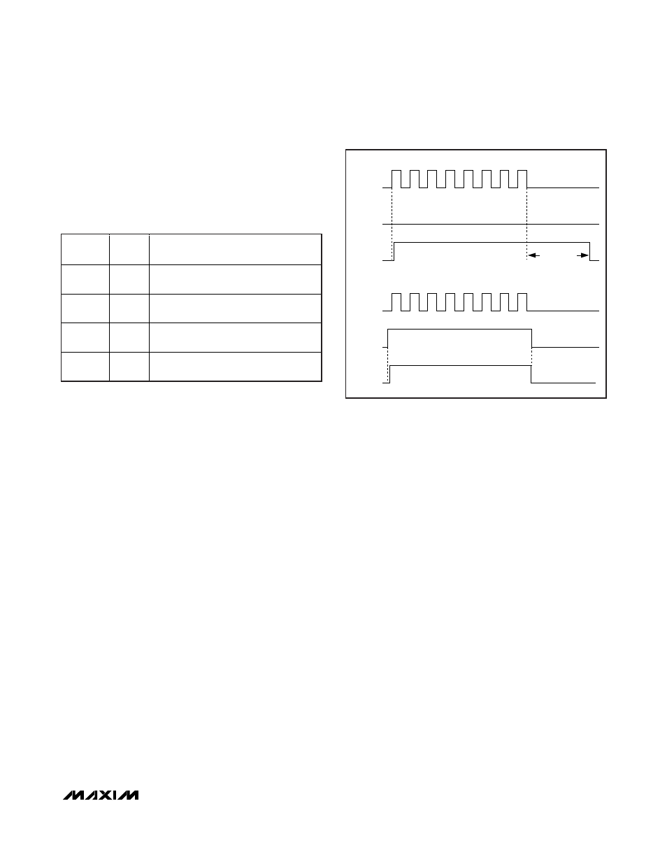
Figure 1. Power-Up Waveform with DIN/ENABLE for MAX7058
DIN
ENABLE
POWER-UP
(INTERNAL)
DIN
ENABLE
POWER-UP
(INTERNAL)
CASE 1: DIN PIN ONLY USED TO POWER UP THE MAX7058
CASE 2: ENABLE PIN ONLY USED TO POWER UP THE MAX7058
FALLING EDGE OF ENABLE MUST COME AFTER
LAST DIN FALLING EDGE
279.62ms
(WITH 15MHz
REFERENCE)