Max7058 – Rainbow Electronics MAX7058 User Manual
Page 10
MAX7058
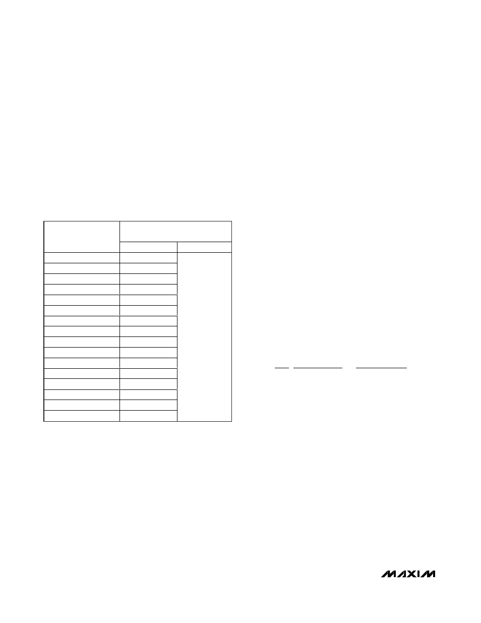
When the particular capacitance control input pin is
high, then the corresponding amount of capacitance is
added at PAOUT; this capacitance tuning works only at
315MHz. The 16 capacitor values are selected by set-
ting CAP1–CAP4; the capacitance resolution is 0.5pF.
The total capacitance varies from 0 to 7.5pF. For exam-
ple, if CAP1 and CAP3 are high and CAP4 and CAP2
are low when operating at 315MHz, then this circuit will
add 2.5pF at PAOUT.
Phase-Locked Loop
The MAX7058 utilizes a fully integrated, programmable
PLL for its frequency synthesizer. All PLL components
including the loop filter are included on-chip. The divide
ratio is set at one of two fixed values: 21 (FSEL is set to
high) or 26 (FSEL is set to low).
Crystal (XTAL) Oscillator
The crystal (XTAL) oscillator in the MAX7058 is
designed to present a capacitance of approximately
6pF between XTAL1 and XTAL2. In most cases, this
corresponds to an 8pF load capacitance applied to the
external crystal when typical PCB parasitics are added.
The MAX7058 is designed to operate with a typical
10pF load capacitance crystal. It is very important to
use a crystal with a load capacitance equal to the
capacitance of the MAX7058 crystal oscillator plus
PCB parasitics. If a crystal designed to oscillate with a
different load capacitance is used, the crystal is pulled
away from its stated operating frequency, introducing
an error in the reference frequency. A crystal designed
to operate at a higher load capacitance than the value
specified for the oscillator will always be pulled higher
in frequency. Adding capacitance to increase the load
capacitance on the crystal will increase the startup time
and may prevent oscillation altogether.
In actuality, the oscillator pulls every crystal. The crys-
tal’s natural frequency is really below its specified fre-
quency, but when loaded with the specified load
capacitance, the crystal is pulled and oscillates at its
specified frequency. This pulling is already accounted
for in the specification of the load capacitance.
Additional pulling can be calculated if the electrical
parameters of the crystal are known. The frequency
pulling is given by:
where:
f
p
is the amount the crystal frequency is pulled in ppm
C
m
is the motional capacitance of the crystal
C
case
is the case capacitance
C
load
is the actual load capacitance
C
spec
is the specified load capacitance
When the crystal is loaded as specified (i.e., C
load
=
C
spec
), the frequency pulling equals zero.
f
C
C
C
C
C
p
m
case
load
case
spec
=
+
−
+
⎛
⎝
⎜
⎞
⎠
⎟ ×
2
1
1
10
6
315MHz/390MHz Dual-Frequency
ASK Transmitter
10
______________________________________________________________________________________
Table 2. Variable Capacitor Values and
Control Input Pins
ADDED SHUNT CAPACITANCE
IN pF
CAPACITOR
CONTROL PIN STATE
(CAP4–CAP1)
315MHz (÷21)
390MHz (ч26)
0000
0
0001
0.5
0010
1.0
0011
1.5
0100
2.0
0101
2.5
0110
3.0
0111
3.5
1000
4.0
1001
4.5
1010
5.0
1011
5.5
1100
6.0
1101
6.5
1110
7.0
1111
7.5
0