C-series dryer control panel – Grain Systems PNEG-573 User Manual
Page 13
13
C-SERIES DRYER CONTROL PANEL
C-SERIES DRYER CONTROL PANEL
C-SERIES DRYER CONTROL PANEL
C-SERIES DRYER CONTROL PANEL
C-SERIES DRYER CONTROL PANEL
3. Press the INCREASE or DE-
CREASE (fig. 2-G, I) button to
adjust the settings.
4. Press the ENTER button to en-
ter new setting into the control-
ler (fig. 2-J).
After the DRY, COOL or UNLOAD
button is pressed, screen messages
on the LCD display of the Electronic
Electronic
Electronic
Electronic
Electronic
Monitoring Control System
Monitoring Control System
Monitoring Control System
Monitoring Control System
Monitoring Control System direct
the dryer operation through the proper
sequence for setting the TIMERS.
During operation the remaining time
on each TIMER is displayed. If the
power goes out or if the dryer is
stopped, these times are saved by the
controller. When the dryer is restarted
the TIMERS will continue timing
down from these times. They will
return to their initial setting if the
RESET button (fig. 2, M) is pushed.
The DRY, COOL and UNLOAD tim-
ers (fig. 2-E, H, K) are used to set
the cycle times in the STAGED
BATCH DRYING MODE only. To
use and display the settings on
these three TIMERS, the DRYING
MODE switch (fig. 1-6) must be in
the STAGED BATCH position. The
current setting on these three TIM-
ERS is displayed directly above
each TIMER button (fig. 2-B, C, D).
To change the setting of these TIM-
ERS follow these instructions:
1. Press the DRY, COOL or UN-
LOAD TIMER button (fig. 2-E,
H, K).
2. Press the MODIFY button (fig.
2-F).
Turn the CONTROL POWER switch
to ON. The monitor will display a
copyright message and model num-
ber, total running time in hours and
minutes and the current time and
date (fig. 2-A). To activate the control-
ler press the RESET button (fig. 2-M).
The Electronic Monitoring Control
Electronic Monitoring Control
Electronic Monitoring Control
Electronic Monitoring Control
Electronic Monitoring Control
System
System
System
System
System (fig. 2) controls all timing
functions and safety circuit checks.
It is designed to simplify dryer op-
eration by providing printed mes-
sages and warnings on its liquid
crystal display (LCD).
ELECTRONIC
ELECTRONIC
ELECTRONIC
ELECTRONIC
ELECTRONIC
MONITORING CONTROL
MONITORING CONTROL
MONITORING CONTROL
MONITORING CONTROL
MONITORING CONTROL
SYSTEM
SYSTEM
SYSTEM
SYSTEM
SYSTEM
SETTING THE DRY, COOL,
SETTING THE DRY, COOL,
SETTING THE DRY, COOL,
SETTING THE DRY, COOL,
SETTING THE DRY, COOL,
UNLOAD AND BATCH
UNLOAD AND BATCH
UNLOAD AND BATCH
UNLOAD AND BATCH
UNLOAD AND BATCH
TIMERS
TIMERS
TIMERS
TIMERS
TIMERS
TURNING ON THE
TURNING ON THE
TURNING ON THE
TURNING ON THE
TURNING ON THE
ELECTRONIC
ELECTRONIC
ELECTRONIC
ELECTRONIC
ELECTRONIC
MONITORING CONTROL
MONITORING CONTROL
MONITORING CONTROL
MONITORING CONTROL
MONITORING CONTROL
SYSTEM
SYSTEM
SYSTEM
SYSTEM
SYSTEM
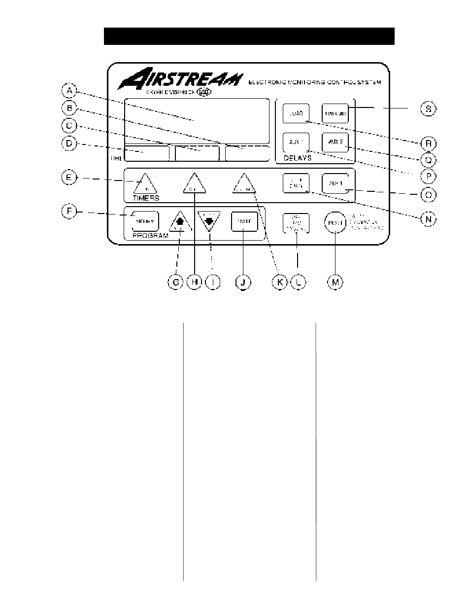
Figure 2: The C-Series Airstream Electronic Monitoring Control System.
Figure 2: The C-Series Airstream Electronic Monitoring Control System.
Figure 2: The C-Series Airstream Electronic Monitoring Control System.
Figure 2: The C-Series Airstream Electronic Monitoring Control System.
Figure 2: The C-Series Airstream Electronic Monitoring Control System.