8 troubleshooting, 1 faults indicated by gateway leds, 2 wired communication faults – VEGA WHA-GW-WIRELESSHART GATEWAY User Manual
Page 88: 8troubleshooting, Wha-gw, Troubleshooting
22
1981
2011
-0
7
88
WHA-GW-*
Troubleshooting
8
Troubleshooting
8.1
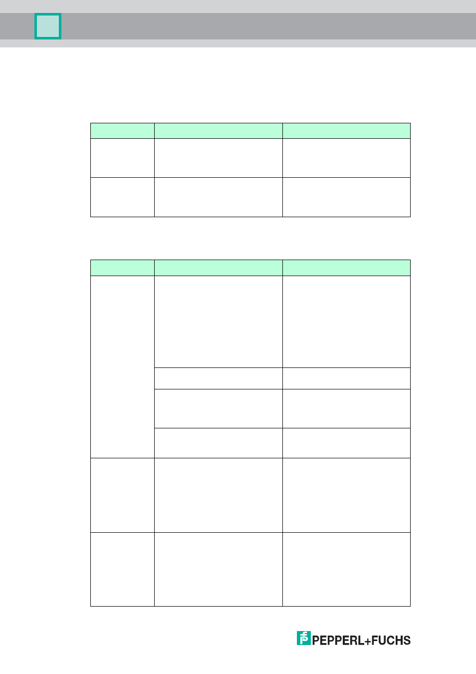
Faults indicated by Gateway LEDs
Faults indicated by Gateway LEDs
8.2
Wired Communication Faults
Indication
Possible cause
Corrective action
Red LED is on
Hardware fault which makes
normal operation of the Gateway
impossible.
Try powering the Gateway down
and up again. If the problem
persists, please return the device
to P+F for repair.
Red LED
flashes
Under certain conditions the LED
flashes while the Gateway
application tries to eliminate the
fault.
Please contact P+F customer
service for guidelines.
Table 8.1Faults indicated by Gateway LEDs
Fault
Possible cause
Corrective action
The host is not
able to
establish an
Ethernet
connection to
the Gateway.
The Gateway is connected to the
Ethernet with a straight through
connection although a crossover
connection is neccesary (or vice
versa).
Access the Gateway's Ethernet
interface (see chapter 2.4).
Interchange the green wire with
the orange one, and the
white/orange wire with the
white/green one. (see Figure 3.10
on page 26). This action changes
a crossover connection into a
straight through connection and
vice versa.
The Ethernet parameters of the
Gateway are incorrect.
Check the Gateway's Ethernet
parameters (see chapter 5.5.2).
The Local Area Connection
Properties of your PC are not
configured correctly.
Configure the Local Area
Connection according to the
instructions given (see chapter
4.5).
If you are parameterizing via the
web interface: Maybe your web
browser uses proxies.
Deactivate proxies in your
browser.
The host is not
able to
establish a
serial
connection to
the Gateway.
Wrong parameters (e.g. COM
port, address range) are set in the
communication DTM.
Check the parameters in the
communication DTM (see chapter
4.6.2). Also check the COM port
configured on your PC(see
chapter 4.4) and the baud
rate/polling address configured via
the DIP switches in the Gateway
housing (see chapter 6.1.2).
The host is not
able to
establish a
serial
connection to
the Gateway, or
the signal
qualitiy is poor.
The terminating resistor is not
activated.
If the RS-485 cable ends at the
Gateway (Gateway is last device),
activate the terminating resistor
via the DIP switch inside the
Gateway housing (see chapter
6.1.2) or via the DTM (see chapter
5.5.1).