VEGA VEGAPULS 45 VBUS User Manual
Page 62
62
VEGAPULS 42, 44 and 45 – VBUS
Adjustment with the PC on the signal conditioning instrument
Outputs
Configure outputs
VEGAMET 514V/515V is provided with cur-
rent, voltage and switching outputs.
VEGALOG enables additional transistor
outputs. Before an adjustment signal is set
(parameter adjustment), it must be assigned
to a particular (configurate), because inputs
and outputs are independent components.
For example, a sensor signal can be
assigned to several current or voltage out-
puts (three per VEGAMET) and the param-
eter adjustment for each output can be
different (0 … 20 mA; 20 … 0 mA etc.). Relay
switching functions, after being assigned to a
sensor signal, are adjusted during the pa-
rameter adjustment, for example with certain
switching routines (dry run protection, overfill
protection, switching points, switching hyster-
esis).
In the following, the configuration of outputs
with the PC is described, which can be natu-
rally carried out also with the 6 adjustment
keys on the VEGAMET 514V, 515V and 614V
signal conditioning instrument. See operating
instructions of the signal conditioning instru-
ments.
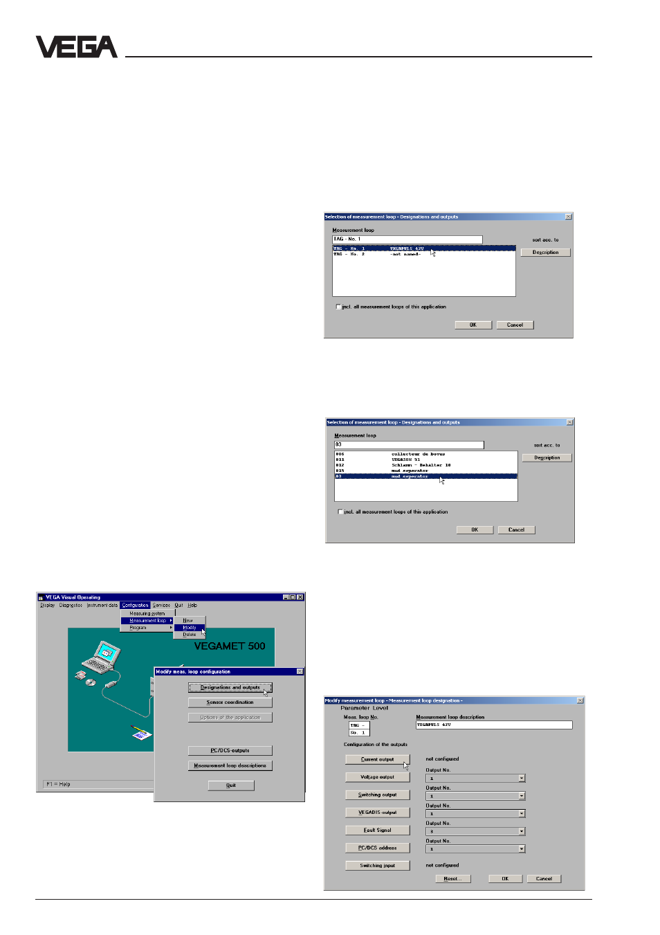
• For configuration of the outputs, choose
"
Configuration/Measurement loop/Modify".
• Click to "
Designations and outputs".
• Choose in the opening window "
Selection of
measurement loop – Designations and
outputs" the measurement loop (sensor), to
which you want to assign an output signal.
For signal conditioning instruments, you
have a choice of max. two (VEGAMET 515V)
sensors or measurement loops.
When using a VEGALOG, this choice can
include a number of measurement loops, as
you will see in the following illustration.
• Choose the sensor or the measurement
loop to which you want to assign outputs.
The menu window "
Modify measurement loop
– Measurement loop designation" opens.
Here you can enter a new name for the meas-
urement loop in addition to assigning the
outputs.