VEGA VEGAPULS 45 VBUS User Manual
Page 44
44
VEGAPULS 42, 44 and 45 – VBUS
Beside the measured values, adjustment
signals are also transmitted digitally via the
signal and supply cable between sensor and
VEGAMET. The adjustment program VVO
can then communicate with VEGAMET and all
connected sensors. In chapter "4.4 Configu-
ration of measuring systems", connection of
the PC to different sensor arrangements is
shown.
Before starting setup:
Do not be confused by the many pictures,
adjustment steps and menus on the following
pages. Just carry out the setup with the PC
step by step and you will soon no longer
need the following instructions. Actions, like
entering a value or making a choice, are
indicated in the following by a large black
dot, like this:
• Choose …
• Start …
• Click to …
• Connect the standard output of your PC by
the standard RS 232 interlink cable to
VEGALOG.
• Now switch on the power supply of the
processing system.
By this convention, the actions to be carried
out are clearly separated from supplemen-
tary information in the following adjustment
instructions.
Start now:
• Connect the standard plug of
VEGACONNECT 2 (9-pole) to the interface
COM 1 or COM 2 of your PC.
• Insert the two small pin plugs of
VEGACONNECT 2 into the CONNECT
socket on the front of the signal condition-
ing instrument.
• Now switch on the power supply of the
signal conditioning instrument.
Adjustment with the PC on the signal conditioning instrument
Usually after approx. 1 … 2 minutes (self-
test) the measuring system is operating and
displaying the measured value.
• Now start the adjustment software VVO on
your PC.
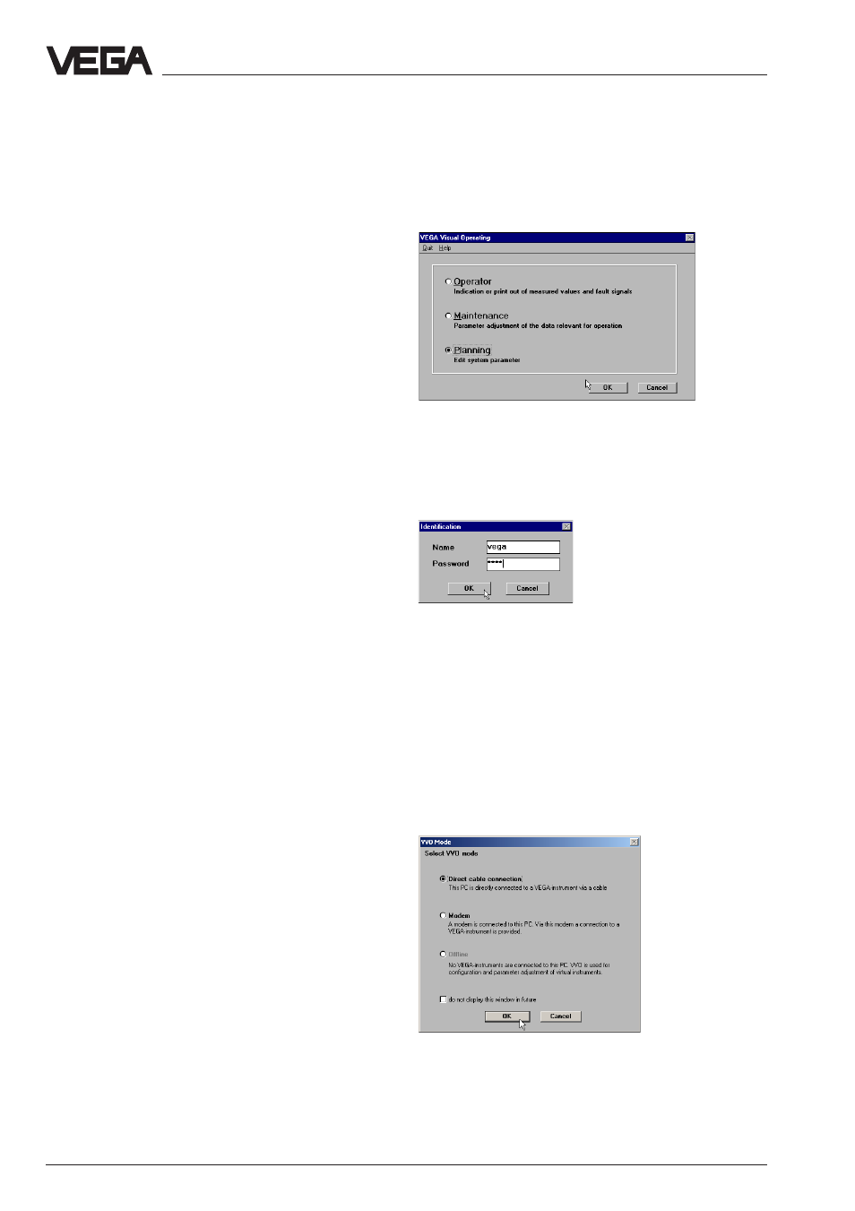
• Choose with the arrow keys or the mouse
the item "
Planning" and click to "OK".
You are asked for user identification.
• Enter under name
"VEGA".
• Also enter
"VEGA" under password.
You are asked for the kind of sensor connec-
tion or if you want to carry out a virtual
adjustment.
• Choose "
Direct cable connection", if your
PC is directly connected to the VEGAMET
via a VEGACONNECT.