Electrical connection, Capacitors – VEGA VEGAPULS 45 VBUS User Manual
Page 37
VEGAPULS 42, 44 and 45 – VBUS
37
Electrical connection
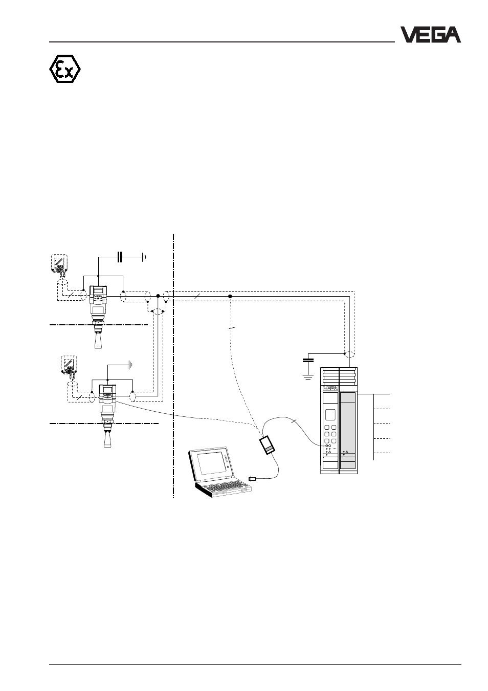
1 … 2 sensors in Ex environment via separator VEGATRENN
548V Ex on the VEGAMET 515V signal conditioning instrument
• Two-wire technology, power supply via separator, output signals and power supply via one
two-wire cable.
• Ex environment acc. to CENELEC and ATEX.
• Digital output signal, two sensors on one cable.
• Display of measured values in the sensor and in the signal conditioning instrument.
• Optional external indicating instrument (can be mounted up to 25 m away from the sensor
also in Ex area).
• Adjustment with PC, signal conditioning instrument or adjustment module MINICOM (can be
plugged into the sensor or into the external indicating instrument VEGADIS 50).
• Max. resistance of the signal cable 15
Ω
per wire, max. 1000 m cable length (see also ap-
proval certificates of the separators).
Note!
In Ex systems, earthing on both ends is not
allowed due to potential difference. It is al-
lowed, however in conjunction with potential
equalisation system or y
c
capacitors.
1)
Sensor wiring should be looped in screened cables.
In case of high frequency interference (> 1 MHz),
it is best to ground the cable screens on both
ends. Please make sure that no earth
compensation currents flow via the screens.
You avoid earth compensation currents (when
grounding at both ends) by connecting the cable
screen on one end (e.g. in the switching cabinet)
via a capacitor (e.g. 10 nF; 1500 V) with the
ground potential.
2
2
4
4
VEGAMET
515V
2
VEGATRENN
548V
Ex area
Non-Ex area
Processings see also Product
Information "Signal conditioning
instruments series 500"
Current outputs
Voltage outputs
Relays
Digital wiring
Fault signals
In case of electromagnetic
interferences, screened cable
should be used (see following
page)
VEGA-
CONNECT 2
VEGAMET 515V signal conditioning instru-
ment with Ex separator VEGATRENN 548V Ex
in housing type 506
Zone 0
or
Zone 1
Zone 0
or
Zone 1
VEGADIS 50
EEx ia
"ia"