VEGA VEGASON 51V…53V User Manual
Page 15
VEGASON 51 V … 53 V
15
Types and versions
-
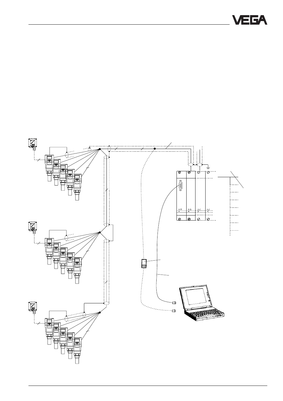
Configuration of measuring systems
15 sensors via one two-wire line on the processing system VEGALOG 571
•
Two-wire technology, power supply and digital output signals via one two-
wire line from the processing system VEGALOG 571.
•
15 sensors on one two-wire line.
•
Measured value indication integrated in the sensor.
•
Optionally external indicating instrument
(can be mounted up to 25 m separated from the sensor in Ex-area).
•
Adjustment with PC or adjustment module
(can be plugged into the sensor or external indicating instrument).
•
Max. resistance of the signal line 15
Ω
per wire or 1000 m cable length.
VEGALOG
571 CPU
VEGALOG
571 EV
2
2
CPU
2
2
2
4
2
4
2
4
Processings see also product information
"Signal conditioning instruments series 500"
Screened line in case of electromagnetic
interferences
1)
Processing system VEGALOG 571
with input cards in 19"-rack. 15
sensors on one module card and
two-wire line
Interface cable
RS 232
VEGASON 51 … 53
(15 sensors per two-wire line
can be individually grouped)
VEGA-
CONNECT 2
VEGADIS 50
Current outputs
Voltage outputs
Relays
Digital wiring
Fault signals
Connection to all Bus-
systems
Transistor outputs
1) Sensor lines should be looped in screened
cables. It is suitable to earth the cable
screens on both ends. However it must be
noted that no earth compensation currents
flow via the screens.
Earth compensation currents can be avoided
with earthing on both ends by connecting the
cable screen on one earth end (e.g. in the
switching cabinet) via a capacitor (e.g. 1
µ
F,
100 V) to the earth potential.