Installation guide, Dimensions, Operation – Veris Industries H8036 SERIES Install User Manual
Page 2: Product identification, Product diagram, Modbus enhanced data stream power transducers, Modbus basic power transducers
Z201686-0N
PAGE 2
©2012 Veris Industries USA 800.354.8556 or +1.503.598.4564 / [email protected]
08122
Alta Labs, Enercept, Enspector, Hawkeye, Trustat, Veris, and the Veris ‘V’ logo are trademarks or registered trademarks of Veris Industries, L.L.C. in the USA and/or other countries.
TM
H8035/H8036
INSTALLATION GUIDE
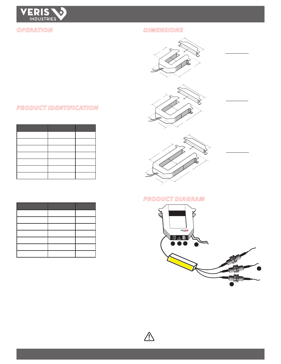
DIMENSIONS
A
B
E
F
C
D
B
E
F
C
D
A
A
B
E
C
F
D
SMALL
100/300 Amp
MEDIUM
400/800 Amp
LARGE
800/1600/2400 Amp
A =
3.8" (96 mm)
B =
1.2" (30 mm)
C =
1.3" (31 mm)
D =
1.2" (30 mm)
E =
4.0" (100 mm)
F =
4.8" (121 mm)
A =
4.9" (125 mm)
B =
2.9" (73 mm)
C =
2.5" (62 mm)
D =
1.2" (30 mm)
E =
5.2" (132 mm)
F =
6.0" (151 mm)
A =
4.9" (125 mm)
B =
5.5" (139 mm)
C =
2.5" (62 mm)
D =
1.2" (30 mm)
E =
7.9" (201 mm)
F =
6.0" (151 mm)
OPERATION
The H8035 and H8036 three-phase power transducers monitor energy parameters
from aggregate kW (real power) and kWh (consumption) to power factor per phase.
Integration of electronics lowers hardware and installation costs. The sensors
automatically detect phase reversal, so CT load orientation is not a concern. The CTs
and electronics are calibrated as a set, so it is necessary to color-match the CTs and
voltage leads when installing. These devices monitor up to 63 loads at a time on a
single RS-485 drop.
With two platforms to choose from (H8035 Basic/Energy Only or H8036 Enhanced
Data Stream), the applications for these devices are diverse, including aggregate
billing, tenant monitoring, energy management, performance contracting, demand
limiting and cooling plant optimization.
PRODUCT IDENTIFICATION
Modbus Enhanced Data Stream Power Transducers*
MODEL
MAX. AMPS
CT SIZE
H8036-0100-2
100
SMALL
H8036-0300-2
300
SMALL
H8036-0400-3
400
MEDIUM
H8036-0800-3
800
MEDIUM
H8036-0800-4
800
LARGE
H8036-1600-4
1600
LARGE
H8036-2400-4
2400
LARGE
*H8036 models work with H8920-1 LON nodes
Modbus Basic Power Transducers*
MODEL
MAX. AMPS
CT SIZE
H8035-0100-2
100
SMALL
H8035-0300-2
300
SMALL
H8035-0400-3
400
MEDIUM
H8035-0800-3
800
MEDIUM
H8035-0800-4
800
LARGE
H8035-1600-4
1600
LARGE
H8035-2400-4
2400
LARGE
*H8035 models work with H8920-5 LON nodes
PRODUCT DIAGRAM
Enercept
®
1
2
3
4
5
6
1. Voltage leads
2. Fuses
3. Modbus connector
4. Status LED: Blink codes: slow green for normal operation; slow red for incorrect
wiring or low power factor (less than 0.5); fast red for maximum current exceeded.
5. Modbus address switches
6. External CTs: Permanently attached; do not disconnect or use with other power
transducers.
Color match CTs and voltage leads! Example: clamp the
red labeled CT around the power conductor connected to
the red voltage wire.