Veris Industries H8036 SERIES Install User Manual
Veris Industries Equipment
Z201686-0N
PAGE 1
©2012 Veris Industries USA 800.354.8556 or +1.503.598.4564 / [email protected]
08122
Alta Labs, Enercept, Enspector, Hawkeye, Trustat, Veris, and the Veris ‘V’ logo are trademarks or registered trademarks of Veris Industries, L.L.C. in the USA and/or other countries.
TM
POWER MONITORING
INSTALLATION GUIDE
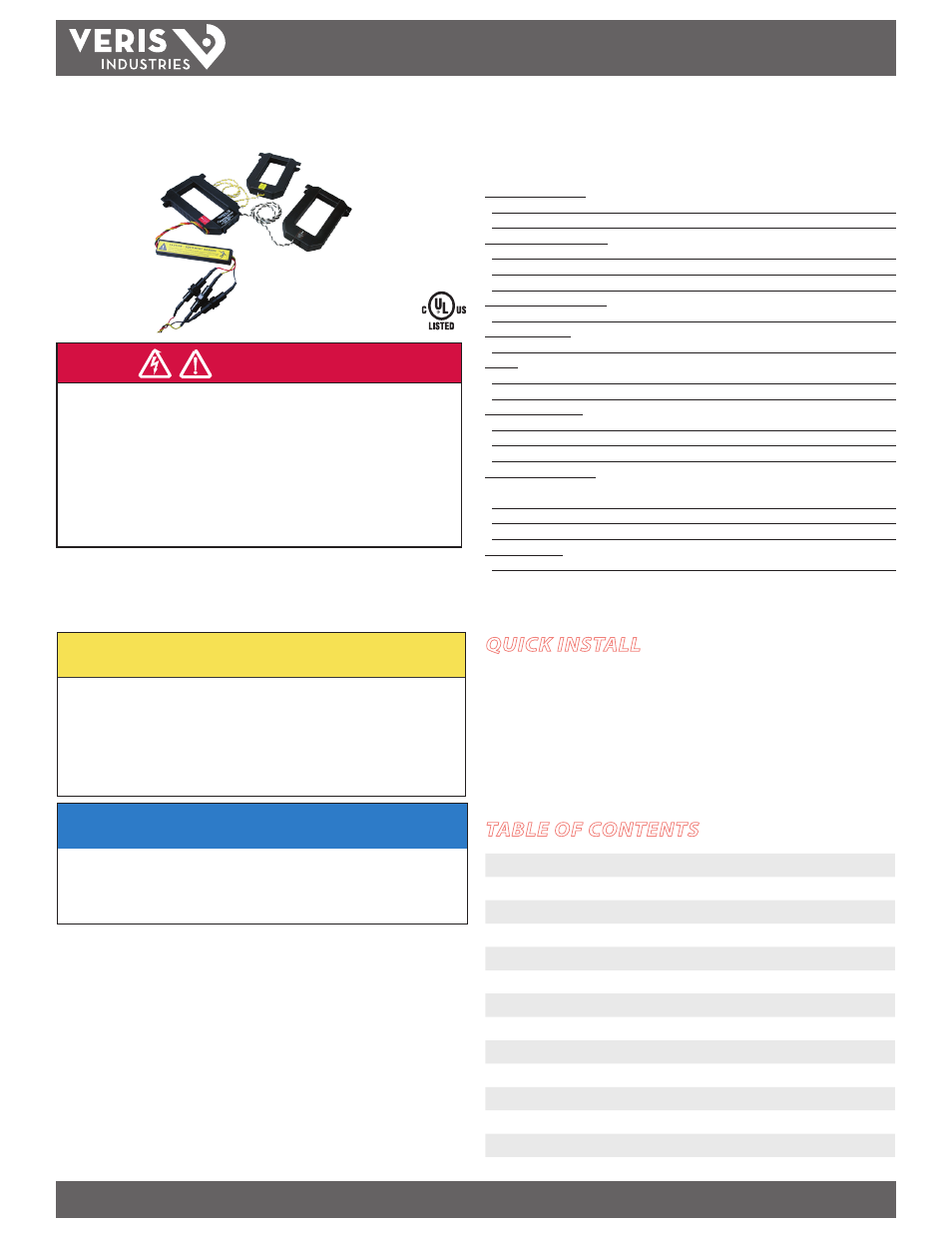
ENERCEPT™ H8035/H8036
Networked Power Transducer (Modbus RTU)
US Patent No. 6,373,238
QUICK INSTALL
Disconnect and lock out power before installation.
1. Set the address switches located on the bottom of the CT.
2. Connect the voltage leads to the source to be monitored.
3. Snap the CT onto the conductor (observe color matching).
4. Connect the Modbus wires (observe polarity).
HAZARD OF ELECTRIC SHOCK, EXPLOSION, OR ARC FLASH
• Follow safe electrical work practices. See NFPA 70E in the USA, or applicable local codes.
• This equipment must only be installed and serviced by qualified electrical personnel.
• Read, understand and follow the instructions before installing this product.
• Turn off all power supplying equipment before working on or inside the equipment.
• Use a properly rated voltage sensing device to confirm power is off.
DO NOT DEPEND ON THIS PRODUCT FOR VOLTAGE INDICATION
• Only install this product on insulated conductors.
Failure to follow these instructions will result in death or serious injury.
A qualified person is one who has skills and knowledge related to the construction and
operation of this electrical equipment and the installation, and has received safety
training to recognize and avoid the hazards involved.
NEC2009 Article 100
No responsibility is assumed by Veris Industries for any consequences arising out of the
use of this material.
DANGER
NOTICE
• This product is not intended for life or safety applications.
• Do not install this product in hazardous or classified locations.
• The installer is responsible for conformance to all applicable codes.
• Mount this product inside a suitable fire and electrical enclosure.
FCC PART 15 INFORMATION
NOTE: This equipment has been tested by the manufacturer and found
to comply with the limits for a class A digital device, pursuant to part
15 of the FCC Rules. These limits are designed to provide reasonable
protection against harmful interference when the equipment is
operated in a commercial environment. This equipment generates,
uses, and can radiate radio frequency energy and, if not installed and
used in accordance with the instruction manual, may cause harmful
interference to radio communications. Operation of this equipment in
a residential area is likely to cause harmful interference in which case
the user will be required to correct the interference at his own expense.
Modifications to this product without the express authorization of
Veris Industries nullify this statement.
CAUTION
RISK OF EQUIPMENT DAMAGE
• Enercept meters are rated for use at 50-60Hz. Do not connect this product to circuits with
high harmonic energy, such as Variable Speed Drives (a.k.a. Variable Frequency Drives,
Adjustable Frequency Drives) or similar sources, as these may permanently damage the
product.
Failure to follow these instructions can result in overheating and permanent
equipment damage.
For use in a Pollution Degree 2 or better environment only. A Pollution Degree 2 environment must
control conductive pollution and the possibility of condensation or high humidity. Consider the
enclosure, the correct use of ventilation, thermal properties of the equipment, and the relationship
with the environment. Installation category: CAT II or CAT III
Installer’s Specifications
Measurement Accuracy:
System Accuracy
±1% of reading from 10% to 100% of the rated current*
Type of Measurement
One or three phase AC system
Input Voltage Characteristics:
Measured AC Voltage
208-480 VAC
Frequency Range
50/60 Hz
Fuses
1/2A, 600VAC, 200 kAIC
Input Current Characteristics:
Maximum Primary Current
100, 300, 400, 800, 1600, or 2400 A, continuous per phase**
Meter Current Draw:
Maximum
60 mA AC
Output:
Modbus RTU Protocol
RS-485, 2-wire plus common
Baud Rate 9600
Mechanical Conditions:
CT Case Isolation
600 VAC
Internal Isolation
2000 VAC RMS
Terminal Block Screw Torque
0.37 ft-lb (0.5 N·m) min.; 0.44 ft-lb (0.6 N·m) max.
Environmental Conditions:
Operating Temperature Range
2400 A model only: 0° to 50°C (32° to 122°F)
all
other models: 0° to 60°C (32° to 140°F)
Storage Temperature Range
-40° to 70°C (-40° to 158°F)
Operating Humidity Range
<95% RH non-condensing
Agency Approvals:
US and Canada (cULus)
UL508 (open type device)
* Meter accuracy specified with conductors centered in the CT window.
** For amperages greater than 2400A, see App Note VN19, www.veris.com/applicationnotes.aspx
TABLE OF CONTENTS
Quick Install
1
Operation
2
Product Identification
2
Dimensions
2
Product Diagram
2
Installation
3
Wiring
4
Data Outputs
4
Address Setup
5
Modbus Register Addressing
6
Using Integer Data Types
8
Notes
10
Troubleshooting
10